 1
1Learning the Internet of Things with
WaterElf, unPhone and the ESP32
Iteration 8 (for Q1 2025, 8.1679.2026-03-10; PDF version; plain HTML; unphone.net).
Copyright © Hamish Cunningham. Licence: CC-BY-SA-NC 4.0. (.js: Christan Hare.)
This book covers Sheffield University’s The Internet of Things course iteration 8, running in Spring 2025. It is intended for students of that course, but should also be useful to anyone studying the IoT and its expression in electronic devices based on microcontrollers in general (and the ESP32 family in particular).
Each chapter begins with general discussion, history or theory, then finishes with instructions for a week’s worth of practical work. Although later material depends to varying degrees on preceding chapters, we have tried to make the order of the practical work as flexible as possible so that you can learn in whatever sequence is convenient for you.2
(The practical work in this chapter and next, though, covers enrolling on the course and setting up your development environment, so please prioritise its early completion!)
So, what is the IoT and where does this course fit in? Read on…3
You made it! You’ve worked hard for years to get this far, and now you get to play :)
As computer scientists and software engineers we spend much of our time with machines whose secrets are hidden beneath multiple layers of abstraction: BIOS, bootloader, operating system, programming language, library API, protocol definition, SDK4, etc. etc. These layers allow us to build systems of incredible power and sophistication, but they also (intentionally) obscure the operation of the underlying hardware engine. This course is a chance to rip the top off the box of tricks, hotwire the starter motor and delve deep into the grungey secrets of the electronic wizardry that makes our discpline possible.
The course is also a way to understand how the latest great wave of technological transformation is streaming into our lives, enabled by the combination of tiny connected microcontrollers, cyber-physical systems and ubiquitous networking. This transformation is driven by the same logic as the explosive consequences of TCP/IP and HTML, but if the last 20 years were about the web, then the next 20 will be about making. Just as always-on connectivity and decentralised production in the virtual world enabled revolutions in creating, sharing and consuming on-line, now the same changes are starting in the world of manufacturing, and the consequences are likely to be massive. (There’s perhaps an 80-20 ratio between economic activity devoted to atoms, or physical processes, in comparison to bits, or informational processes.) In the IoT there’s still a space to get in on the ground floor, and learn how to make with the foundational hardware of the next wave.
Hang on to your hat; the future is a whirlwind!
Actually there are two :(
First, you’re going to be programming a tiny little device that has, in comparison to that shiney laptop on your desk or that smartphone in your pocket, close to zero computational resource. There’s no paging, for example, so in the sense of time sharing (first developed in the 1960s) our devices don’t even run an operating system! This can be a challenge. Be prepared.
Second, ideally you’re going to need to install an SDK of one sort or another on your own machine, because you need to be able to spend concentrated hours playing with the beasts, and there’s nowhere better than your own computer for experimenting.
To help you with these challenges we will:
If you don’t have a machine that you can use for this and need something cheap, you might try a Raspberry Pi 4 or better (preferably an 8GB models), which are very capable of running the basic IoT SDK that we work with.
If you’ve already got a machine running MacOS or Windoze don’t panic:
And: look on the bright side, the more you do, the more you learn :) (And: DevOps is a thing.)
Actually I lied: there are three catches:
As the perpetual beta style of service-oriented computing moves into physical spaces, we’re all at the mercy of suppliers’ willingness to use us as guinnea pigs – only this time our homes and our clothes and our handbags are the venue of choice.5 Will the future of the IoT be dominated by botnets and fraud? Or will we use the new machines to help face up to the massive survival challenges that a finite world poses to an expansionist system? I think you’re part of the answer.
As humanity’s latest pandemic swirled across the world, wreaking havoc on the poor, the old and the unlucky (and giving the powerful their latest excuse for moulding us all into yet more profitable shapes), some small comfort could be found in the contemplation of the intricate. The history of machines is part of what distinguishes our species: cooperating to create the preconditions of our existence using ever more sophisticated engines.
Computational engines have brought a new level of generality to the picture: Turing machines exemplified by von Neumann architectures and running on some millions or billions of transistors have become a universal mechanism for information processing and automatic control, and collectively we are deploying more and more compute power, memory and storage at a truly astonishing rate. The extreme expression of this tendency is cloud computing, to the degree that it is now hard to imagine a compute problem which would exceed the combined power of the modern cloud. (ChatGPT is a striking example of the revolutionary consequences of coupling this power with the accumulated data of several decades of web and social media data collection. Not a general AI, but something that sometimes does a very convincing imitation of one!)
At the opposite extreme from the general purpose computer are those engines that are tailored (ever more precisely) to a specific purpose. These machines, in the limit, form minimal solutions to complex problems. There are few fields that exhibit this minimalism as purely as what is now called the Internet of Things6. As computation has permeated almost all corners of technology a particular class of problems has become prominent, where we seek not generality but to consume the smallest viable quantity of resource. The use cases for a general purpose machine are always expanding and we can always, potentially at least, justify the devotion of more resource to their construction. In contrast, the uses case for the Internet of Things are inextricably tied to objects whose sizes, costs and operational environments present a constant resource challenge, and a constant downwards pressure on compute cycles and power consumption.
Computing, then, has two souls: the general and the specific. This book argues that the IoT is firmly part of the latter. Serendipitously, this soul uses as little planetary resource (and our precious attention) as is possible. Reduce, reuse, recycle (and repair, and reclaim, and recover, and… well, the time for action is now!).
The solutions that we build in the IoT are beautiful in their intricate simplicity, minimal expressions of the vast power of our universal machines, and their “…perfection is attained not when there is nothing more to add, but when there is nothing more to remove”7.
Of course we don’t always achieve minimalist elegance on our first tries. Heath Robinson captured the feeling I have when I look at some of my previous attempts at IoT devices:
This course is about transforming our computational selves from high priests of the general purpose to paragons of minimalism (probably via the joyfully messy intermediary of Heath Robinson).
Enjoy the ride!
We will come to the question of how to think about the various types of hardware used in the IoT many times during the course. To begin with, suffice it to say that IoT devices use network-connected microcontrollers. (They may be interfaced to IoT hubs and gateways, which generally use ARM microprocessors, but for our purposes the key innovation and core hardware is the networked microcontroller.)
For this course, we will use a microcontroller called ESP32, which although a relative newcomer has become very popular over the last half decade or so. It is relatively cheap and it’s firmware ecosystem is very open by industry standards. Every student on the course gets an ESP32 development board9, and programming it is a core practical skill that we aim to teach here.
Feel free to read more about the chip now, or wait and see :)
What if we wish not simply for the comfort offered by contemplating (and, later, controlling) the miraculous intricacies of task-specific computational engines, but also for hope?
Take a minute. Switch off your phone. Look at the objects around you, remember the food on your plate at your last meal, feel the warmth of your clothing, the security of the building you are sitting in. The economic system that creates all of these things, all of these preconditions for your existence, is driven by a single imperative that equates profit with value. When that equation is combined with the vast and impersonal forces of transnational corporate competition the results are well known. We use our atmosphere as a sink for the carbon remains of an aeon of decayed flora and fauna. We use each other as expendable “human resources.” We crowd sick animals together in zoonotic melting pots and express surprise at the apocalyptic consequences.
In this somewhat gloomy context there are nevertheless several glimmers of hope connected to the IoT… but allow me, dear reader, a little suspense in my narrative: we’ll come back to how to save the world after we’ve done some of the spade work. Watch this space :)
The course (like life) has two sides, practical and theoretical10. The practical work is split in two halves:
We provide information via three main channels:
(There is also a small amount of administrative information on the University Blackboard page for the course; make sure to check it out.)
There is a notes section for each week of the course12. Each chapter ends with a “week N course notes” section describing our objectives for this part, and specifiying practical work that we want you to complete. By and large you can read the first parts of the chapters in lean-back mode: they are discursive, and intend to give a flavour of the field and its historical and technical contexts. The latter parts of the chapters are more directive, and you’ll need to sit at a keyboard and follow instructions; the intent is to lead you to practical outcomes and running code.
There is example code in the exercises tree of the course materials repository. This code covers many of the tasks that we ask you to complete week by week. You can, of course, copy the answers without trying to come up with your own solution, but you will learn little by doing so. The recommended method is to implement your own answer to the exercises, then go to the relevant example code and compare it with yours.13
This is a 10 credit (level 3) module; this means about 100 hours work. It is taught over one semester, so it averages out at about 7-8 hours per week. (Depending on your existing skills and previous experience you may need more or less time.)
This is iteration 8 running in 2025.
Last year’s course was the best ever according to student feedback, so we’re going to keep most things the same this year.
One exception is that as the global race to spawn trillionaires continues to suck up resources like a mindless black hole, so our own local version of austerity now prevents us from giving away the project hardware as in previous years :(
Luckily we are still able to give away expansion boards for unPhone based projects :)
Other updates are similar to last year:
You lucky things.
IDF and Arduino core versions: we’re still using 4.4.x and 2.0.x releases while waiting for 5.x.x / 3.x.x (the latter will likely need a fair bit of migration work). Versions 2.0.6 (a little old but quite stable) and 2.0.14 (the latest of the 2.x line, bringing with it IDF 4.4.6) of the core should both work.
This was iteration 6 running in 2023.
Changes:
This was iteration 5 running in 2022.
The previous run, iteration 4, with almost no lab sessions, went better than expected :) (The student feedback we collected is available from Blackboard.)
There were a couple of things that glitched a little:
In 2022 we’re making these changes in order to address those two issues:
In addition, I’ve significantly simplified the support tooling (specifically the magic.sh shell script), and added the ability to use the tooling via Docker to make cross-platform working easier.
I hope you like it! (If you do, tell others, if you don’t, tell me ASAP and I’ll try to fix it!)
We needed to change quite a lot from last time the course ran! The 2021 version relies on 3 Ts: Toys@home, lots of Text, and Tech support :)
Threshold and grading works by separating the process of passing the course from the process of attaining a good grade. The threshold assessments check that you have a basic understanding of all the material; the grading assessment evaluates the quality of that understanding in depth.
The course is assessed by two practicals (lab1, lab2) and a (multiple choice) exam. Lab1 happens at week 7 and lab2 at week 12 (and the exam during the standard exam period at the end of the semester). (A mock exam during term will allow you to practice the material.)
You must pass lab1 and the exam in order to pass the course. This will give you a score of 40%. In order to score more than 40% you must also complete lab2, the project.
Lab1 and the exam are assessed as pass/fail only (and no score is given for lab1). A pass in both contributes 40 marks to your final result.
Lab2 is a project which students spend several weeks completing at the end of the course. The assessment is open-ended and qualitative in nature. It is marked out of 100 and contributes a maximum of 60 marks to your final score. Lab2 is assessed in similar manner to Lab1, so feedback from the Lab1 can guide you in performing Lab2 (with the exception that the latter has around four times more time available for your work, and therefore should be commensurately bigger).
This is an advanced course and the project assessment in particular is intentionally open-ended. There is no single right answer! If you’re unsure about how much effort to expend the rule of thumb is to put in as many hours as is reasonable for a 10 credit module (see above; perhaps 8 or 10 hours per week).
We’ll give more detailed guidance in relation to each of the assessments as they occur; the things to remember to begin with are that:
This section describes stuff to do before you start the course:
1. We will communicate with you using Git and GitLab, both to deliver course materials and assignments to you, and for you to submit coursework to us. Therefore you are not fully enrolled for the course until you set up an appropriate git repository and give us the details. Do this ASAP!
2. Spend some time getting to know git and the other tools we’ll be using. (The Linux command line is powerful, elegant and, to newcomers, challenging. Using git from the command line adds another set of challenges. A bit of preparation will help!)
3. Refresh your memory of the Diamond Electronics lab safety protocols. You cannot participate in lab sessions without having completed the safety work.
Details follow.
NOTE: the images below say “2021” in them, whereas you need to use “2025,” and there are a few minor changes in the current version of GitLab.
First register an account on GitLab.com if you don’t have one already. Use your Sheffield email address (ending in @sheffield.ac.uk) to register. (NOTE: be sure to use https://gitlab.com/ and NOT the Sheffield-based GitLab server, which is being phased out.)
Second, create a private repository (project) there (from the “blank project” option) called com3505-student-2025:

(Make sure to select the Initialize repository with a README option.)
Third, go to the Project Information members settings…

…and add hamishcunningham…
")
…as a project maintainer:
")
Lastly submit your GitLab user name to our server (see next section).
Your user name (or “ID” for our purposes) is the name you log in with, and appears in the URL of the site when you’re logged in. For example, Hamish’s user name / ID is hamishcunningham and his public GitLab projects appear at gitlab.com/hamishcunningham (and GitHub ones here, and SourceForge here, and Docker images here…).
We need to know your username and match it up with your student record so that we can pull the coursework that you commit there. Tell us your username by filling in the form linked from the Blackboard page.
Note: don’t send your numeric ID from GitLab, but the alphanumeric user name / path that appears in your project URLs. (Mine is hamishcunningham.)
To create and deliver the course we use most or all of the following tools. You can follow the course without using the command line, but we recommend learning it if you can; it is debatable that you’re ever really in control of a machine for which your only interface is a GUI (especially when that GUI is closed source).
It is a good idea to get to know at least Git and if possible the ESP and Arduino tools before starting (though you should be able to pick them up as we go along if needed).
In addition we will need a code editor or Integrated Development Environment (IDE) for writing IoT device firmware in C and C++, e.g.:
We’ll cover how to set up these tools next week.
Parts of the practical work for the course are best done in the Diamond Electronics Laboratory (DIA 2.02), and we have sessions available each week of the course in 2025. You are also entitled to use the facilities in the iForge (the Diamond 1.01 project space, see next section) if you need more time, though do make sure to register with them before trying to gain access.
The electronics lab is a fantastic learning environment, and we give you as much time in there as we can during the course. It is also a potentially dangerous environment. Before coming to any lab session you must do the following:
Soldering is optional this year (but definitely a useful skill for IoT prototyping); if you want to do soldering in the lab, please also watch this tutorial video and see section 3 of this lab intro.
Please follow University guidelines relating to covid-19 at all times!
The iForge is the University’s student-led makerspace that provides workshop and making facilities outside the scope of your degree. If you would like to use the iForge there are a couple prerequisites:
If you would like to find out more about the iForge feel free to check out their linktree or head to DIA 1.01 to find out more in person.
Have you done the preliminaries?? If not, now would be a good time :)
Our objectives this week are to:
The assessment of your practical work on the course is delivered by checking in to your git repository and pushing to the “origin remote” (on gitlab.com). If you don’t push anything, we won’t be able to give you feedback or to mark your work, so it is important to get used to this system early on.
Check out your repository from gitlab into your own file space (the first time you start work on a new machine):
git clone ...url..., for example: git clone https://gitlab.com/YourGitLabUname/com3505-student-2025.gitOther common commands:
git status to tell you what the current state of your file tree is, and git diff to show detailed changesgit add file-pathgit commit -vam 'a commit log message'git pushgit pullNote: git (and GitLab / GitHub) have become industry standards in recent years, so it is important for you to get to know at least the basics. However, an independent survey of experts recently estimated that of 2,153 git command options, fully 213% were either contradictory, confusing or error-inducing (or all three). [I may have made that bit up.] It is depressingly easy to get git into a mess! [I didn’t make that bit up.] What to do? Here’s one way to escape from git hell…
Let’s say you have conflicts in your com3505-student-2025 repository and the process of resolving them is proving difficult. To re-create a clean version of the repository (in your home directory):
cd
mv com3505-student-2025 saved-repo
git clone https://gitlab.com/YourGitLabUname/com3505-student-2025.git
You’ve now got a fresh copy to work with; if you have changes in the saved version you can copy them over to the new, then commit and push from there.
Yes, it was called ‘git’ for a reason…18
This section describes what to do in your first lab session:
If you finish early you might also want to learn about measuring simple values (using the multimeters and/or oscilloscope), but this is optional.
The hardware kits give you an ESP32 net-connected microcontroller, sensors and actuators, and the means to prototype experimental circuits: the foundations of IoT hardware.
For reference each kit should contain:
(In the second half of term we’ll give you additional hardware for your project as necessary. Enjoy!)
shell or bash, often running in a terminal) to do many of our tasks. On MacOS an old version is available by default; update like this. Ports of these tools are also available for Windows (try Cygwin, Git Bash, Windows Subsystem for Linux, or perhaps an Ubuntu VM or a container via Qemu, LXC or Docker). If you find these tools difficult then please read up on them and practice. See also the links about tools above.When you can measure what you are speaking about, and express it in numbers, you know something about it; but when you cannot measure it, when you cannot express it in numbers, your knowledge is of a meager and unsatisfactory kind: it may be the beginning of knowledge, but you have scarcely in your thoughts advanced to the stage of science. (William Thompson)
Not everything that counts can be counted, and not everything that can be counted counts. (Albert Einstein)
Low cost networked computers are adding eyes and ears (or sensors) and arms, legs and voices (or actuators) to the Internet. These new devices are being connected to on-line brains (big data and deep learning in the cloud)20. This new field is the IoT, of course. Will the result be a ‘world robot’ (Schneier 2017)?! This chapter will start to cover some of the context and history of the IoT. Chapters that follow will cover the hardware that makes it possible, the communications protocols and security systems it relies on, and the cloud-side analytics that make sense of the data it produces.
The practical work this week is to getting to know the SDKs and IDEs21 that allow us to develop software (or firmware22) for the net-connected microcontrollers that are the foundations of IoT devices.
We’ll begin with a couple of definitions, then look at the genesis of the software ecosystem that we’ll be using to program our IoT devices, before moving on to the practical question of development tools.
There are many definitions of the Internet of Things (IoT); one of the most exciting is given by Bruce Schneier in his provocative piece Click Here to Kill Everyone:
…the Internet of Things has three parts. There are the sensors that collect data about us and our environment… Then there are the “smarts” that figure out what the data means and what to do about it… And finally, there are the actuators that affect our environment. … You can think of the sensors as the eyes and ears of the internet. You can think of the actuators as the hands and feet of the internet. And you can think of the stuff in the middle as the brain. We are building an internet that senses, thinks, and acts. This is the classic definition of a robot. We’re building a world-size robot, and we don’t even realize it. (Schneier 2017)
At the other extreme the IoT is about what becomes possible when networked microcontrollers become cheap enough to embed in very many everyday contexts, from central heating thermostats to garage doors. These devices face tight constraints of power usage and cost, and concomitant challenges to their security and functionality. They also quickly become extremely numerous, driving work on big data analytics and cloud computing.
The technology of networked devices goes back perhaps 50 years or more. The coining of the term itself is often credited to Kevin Ashton in 1999, while working at the Auto ID Center at MIT (Ashton 2011), of which more later.
If we understand the past we stand a better chance of seeing into the future. Where did the IoT come from? Where did the systems we’re going to be coding with come from? Later on we’ll learn about an embedded electronics ecosystem that brought the needs of Italian artists together with the origins of the operating system that drives much of the internet and the compiler suite that has been ported to more architectures than any other… and spawned the Arduino.
But first: do you own a phone?
You are very probably carrying a phone, but do you own it?! Call me an old stickler, but I think that if I own something then:
Do those things apply to your phone? How about your laptop? Your tablet? In the 2020s we often pay for electronics which the people who sell then claim we will own, but if we take the trouble to read the licencing documents that accompany them we often find that we have few rights over them, and that repair, for example, is expensive or difficult or voids the manufacturer’s warranty. Much of the electronic and computational ecosystems we’ll spend most of our time with in this course arose from a similar realisation some 50 years ago.
Back when I was a wee small snotty thing, and many of you were only minute folds in the quantum potential of possible future universes, the PDP 10 was a cool computer:
It was the first machine to make time sharing (or multitasking) common, and it had a huge maximum memory of… a whole megabyte!24
The operating system code (assembler) on the PDP 10 and its immediate cousins was routinely shared and improved by a community of programmers (or “hackers”25) at MIT, including one Richard Stallman.
As computing companies became bigger and more profitable in the 1980s practices began to change: there started to be no more access to source code, and users would have to sign an NDA26 even to get access to a binary. Stallman suffered the consequences of an aversion to NDAs when he was refused access to the source for a printer control program, even though his intention was to improve that program. He says: ‘This meant that the first step in using a computer was to promise not to help your neighbor. A cooperating community was forbidden. The rule made by the owners of proprietary software was, “If you share with your neighbor, you are a pirate. If you want any changes, beg us to make them.”’ (Stallman 2002)
’So I looked for a way that a programmer could do something for the good. I asked myself, was there a program or programs that I could write, so as to make a community possible once again?
The answer was clear: what was needed first was an operating system. That is the crucial software for starting to use a computer. With an operating system, you can do many things; without one, you cannot run the computer at all. With a free operating system, we could again have a community of cooperating hackers—and invite anyone to join. And anyone would be able to use a computer without starting out by conspiring to deprive his or her friends.’ (Ibid.)
And this is what lead to the kernel code that runs your Android phone, the GNU/Linux operating system that runs the majority of servers in the cloud, and the compiler code you’ll use to create firmware to run on the ESP32 in this course…
Why does this matter?
And, perhaps most important of all, we have been describing the genesis of the whole free and open source software movement, which has been responsible for huge portions of the code running our world, and which in combination probably constitute the most complex machine ever constructed. Where will it go? Where will humanity go, locked into a triple crisis of pandemic, environment and economy? The two questions are (perhaps uncomfortably) tightly linked.
Ok, enough context for now. We’ll come back to IoT history next week; now for something practical :)
When we write code to run on a microprocessor (e.g. on your laptop, phone, or that Cray you have in the garden shed) we use all the facilities of the operating system, a modern programming language and its library ecosystem to insulate ourselves from the underlying hardware and to provide a set of abstractions, APIs and components that can make us productive at high speed. In recent times we have started adding on-line cloud APIs to the mix, making our potential deployments of computational resource truly vast.
On a microcontroller like the ESP32 in your kits, we have a lot less support: programming is typically with low level languages (C, C++, occasionally bits of assembler), the ‘operating system’ is more like a task management library, and the development tools are often cranky and basic. Firmware usually has to be uploaded to the device over a serial line or JTAG connection, and the tooling to perform this task is different for every hardware family.
In some cases a new world of Javascript or Python programming and drag-and-drop upload (e.g. over USB mass storage class) is starting to become available for the IoT, but:
The second of these points in particular means that projects that need to use the hardware efficiently and to exploit all of the available facilities will most often write in C/C++.
(Not convinced? See Appendix B for how to use Python on the Feather S3 and the unPhone. In fact Python is becoming a good choice for IoT prototyping at least, especially if you already know it.)
This section begins by looking at the basic (toolchain, SDK and library) building blocks of development on the ESP32, then goes on to describe available development environments. Later on (section 2.6.4) will talk you through installing your own development environment and taking your first steps in programming an IoT device.
In any novel embedded system the foundational step is to port a C compiler to the new chip. The compiler, linker and the tools that take a binary image and burn it into the memory space of the device (in a form that can then be sucked up by a bootloader and turned into a running process) are called collectively the toolchain. The compiler is generally an unusual beast, as it has to run on one platform (your development machine, x86_64 perhaps) but produce binaries for a different architecture (Xtensa being the one on the ESP32 in your parts kit, or RISC-V the coming thing); i.e. we need a cross compiler. So when installing a development environment for the ESP32 we need to pick up the Xtensa port of GCC (the GNU Compiler Collection, aka GNU C Compiler).
There’s good news and bad news about this step:
There are snakes in the long grass, wear your wellingtons.
A compiler, when ported to an IoT microcontroller, will open up the magical gates of productivity and allow you to do… not very much at all! The differentiators between the (many) different chips competing for IoT oxygen relate to their hardware facilities, and to access these we almost always need more than is provided by the standard C library. (On the smaller, more resource-constrained devices, the standard library may not even be present due to lack of space; in the case of the C++ library this is actually quite likely.) In order to sell chips, then, the microcontroller manufacturer needs to supply a set of libraries that expose the hardware functionality of its wares in as friendly and powerful a way as possible.
On the ESP32 there are two main layers that we will be dealing with in some detail (and a third which we’ll touch on here and there):
We’ll describe each of these in the rest of this section; section 2.6 below will start us off on the process of installing and running the various SDKs, libraries and development tools that we need to learn.
Espressif, maker of the ESP32, provides an SDK and library set called ESP-IDF, or Espressif IoT Development Framework, whose development is hosted as open source on GitHub (Oner 2021).
ESP-IDF has grown to be a large and successful open source project that incorporates ports of many other libraries to ESP hardware. For example, MbedTLS (source code) is a very popular small footprint cryptographics library (supporting certificate-based security and the TLS protocol that underlies security on the web via HTTPS). Espressif support a port of MbedTLS (documented here, source here) that exploits the ESP32’s hardware acceleration facilities for tasks like random number generation or hashing. This hides the peculiarities of the ESP’s underlying hardware from the programmer, who can instead use familiar and well-documented abstractions as surfaced by the MbedTLS library.
Other libraries that are supported for the ESP32 via ESP-IDF include:
lwip: a complete TCP/IP stackspiffs: filesystem over the SPI protocol (for flash RAM)protobuf-c: protocol buffers serialisation formatmqtt: the MQTT publish-subscribe messaging protocolcoap: the CoAP communication protocolIn each case IDF adapts the library to particularities of the underlying hardware, making it easier for programmers to exploit the chip to its full potential without learning about the grungey details of which register does what under what conditions.
Whenever we write code for the ESP32 we will be using ESP-IDF APIs, either directly or indirectly. To begin with, the easiest way is to use them indirectly, letting the Arduino compatibility layer take the strain (see below).
As of early 2025 there are two main versions of IDF that we will come across:
From version 4 IDF changed its principal build system from GNU Make to CMake, and this has made supporting multiple versions quite complex. (In version 5 GNU Make is deprecated.) There are three scripts provided by the distribution that set up the environment needed for the build systems to work:
flash (to burn firmware) and monitor (to listen on serial); this lives somewhere like ~/esp/esp-idf depending on how you’ve set up the install (~/the-internet-of-things/support/tooling/esp-idf if you’re using the setup scripts supplied for this course)IDF_PATH, the location of the IDF file tree; this also lives in esp-idfvenv (virtual environment) script that sets up PATH etc. to pull in the requisite flavour of Python; this lives in ~/.espressif; a common cause of errors is that the virtual environment gets out of sync with the rest of the IDF install29Each of these has changed and evolved over different versions of IDF, and they present a difficult moving target to IDEs and automation scripts like Eclipse, PlatformIO and VSCode. (It is also a rapidly changing system integrating many 3rd party libraries.) This means that it has previously been quite challenging to get a 4.4.x IDF setup working with the Arduino layer. Luckily this has mostly passed, with the 2.0.6 release of the Arduino core being based on 4.4. We’ll start with 2.0.6 for our work; versions through 2.0.14 should also work fine.
An additional complexity is that IDF provides a configuration tool, menuconfig (based on the KConfig language), originally developed for the Linux Kernel. This exposes many of the optional features of IDF and of the libraries it incorporates. To use it you have to be doing a native IDF build of one type or another (which means you can’t easily use it in the Arduino IDE). Some of its capabilities are mirrored in configuration that is exposed by the Arduino core, but not all.
Another important facility that we can access via the Espressif SDK is FreeRTOS, an open source real time ‘operating system’. FreeRTOS provides an abstraction for task initialisation, spawning and management, including timer interrupts and the ability to achieve a form of multiprocessing using priority-based scheduling. The ESP32 is a dual core chip (although the memory space is shared across both cores, i.e. it provides symmetric multiprocessing, or SMP). FreeRTOS allows us to exploit situations where several tasks can run simultaneously, or where several tasks can be interleaved on a single core to emulate multithreading.
This doesn’t necessarily make life simpler! Most microcontroller code, at least in the hobbyist and maker spaces, is written to target single core chips, and the potential for shooting yourself in the foot rises very quickly when trying to adapt to a world where multiple things may be happening (or at least seeming to happen) all at once. Who owns this piece of memory? What will happen when two tasks both try and talk over this bus? Why does my code behave differently if I pause a task for a few microseconds? To begin with at least, it may be easier to limit yourself to a single task that runs an infinite loop, and worry about FreeRTOS later on. (This is what happens, in fact, when we delegate our main program entry point to the Arduino “core” for ESP32: the setup and loop procedures which characterise Arduino programming are implemented for us using a FreeRTOS task, but we don’t have to worry about the details.)
Later on, interrupts, tasks, event queues, mutexes and semaphores will all become objects of interest, and if you’ve a mind to dive into the mysteries of FreeRTOS that’s where you’ll find them. Enjoy!
Fairly early in the lifetime of the ESP32’s predecessor chip, the ESP826630, a Bulgarian developer going by the somewhat cryptic moniker of me-no-dev decided that what was needed was integration with the Arduino ecosystem. He set out to develop a compatibility layer between Arduino libraries and development tools and the ESP8266. The work rapidly captured the imagination of a large number of developers, and has become a mainstay of the ESP community: nowadays there are commits from more than 500 people in the github repos, and perhaps 10,000 commits overall. Espressif could see that this was a good thing: they hired me-no-dev and he now works full time on the “Arduino core” for the ESP32. The project can be found here.
What’s an Arduino core when it’s at home? I’m not sure where the term originated, but it basically means all the code that interfaces a device and its toolchain, compiler settings, and libraries to a) other Arduino library code and b) the Arduino IDE. This piece of kit is incredibly useful, because the Arduino ecosystem is massive. Pick up any electronic component (sensor, actuator, dog brush or kitchen sink) and the likelihood is that someone has published an Arduino-compatible library for it. This makes programming from the Arduino APIs hugely more productive than otherwise, because we’re almost always working from widely used running code. Win win win!
Motherhood, apple pie, happy ever after. Except: VERSION HELL!!!
When we program the ESP32 we’re typically using C code from ESP-IDF, C code from the libraries that have been ported to the ESP chip family and included as part of ESP-IDF, C++ code that translates between ESP-IDF and the Arduino APIs, and C++ code that exposes sensor and actuator hardware within the Arduino ecosystem. (All of these are in active development, and all have their own release cycles.) We are then compiling this morass with a toolchain that has its own version trail, controlled by a build system that comes in a whole bunch of different and subtly incompatible flavours and, finally, uploading it to the IoT device using a Python script written in … erm, Python (possibly one of the least stable programming languages ever devised31).
Hmmm.
The types of things that tend to go wrong are:
idf.py script from Espressif, custom scripts provided by library developers, the Arduino IDE or CLI, PlatformIO, VSCode, Eclipse, …) expects one shape of file tree, but in the current version things have changedSo: if things go wrong, don’t worry. You’re not alone. Section 2.6.4 tries to map out a path of relatively easy and reliable options. But first, let’s round off this discussion with a look at the available build system CLIs and IDEs.
The game, lest we forget amidst all this gratuitous verbiage, is to (cross-)compile our code against 1001 IoT and embedded systems libraries and burn the resultant firmware images to an ESP32. Along the way it might be nice to throw in a bit of:
We have two main families of options for doing (some subset of) these things:
Examples of IDEs include:
gUw and ZZ and :r! column -t. All the best people use it.Examples of CLI build systems include:
I was talking to someone recently who works at one of the big semiconductor companies (the one that specifies the architecture used by the chip in your phone) about the difference between microcontrollers and microprocessors and remembering all the weird challenges that the former tend to throw at you. “Welcome to embedded,” she smiled, where getting your toolchain installed can be a week’s work :)
We’ve looked a little at the complexity of the development ecosystem for typical IoT (net-connected microcontroller) devices, and mentioned the plethora of support tools that are available just for the device which this course is based on. Before we move on to practical work, a digression on solving the cross-platform problem for these tools.
Many embedded system projects use some variant of Linux as their host environment. Linux is the only widely-used operating system in which predictable and repeatable builds are straightforward, and the only environment where we can be confident that we’re using a maximally open (and auditable) codebase. The support tools we provide for this course (e.g. magic.sh) require the core GNU/Linux toolset to work.
What if we’re forced to use a different platform, e.g. Windows or MacOS? There are many answers, going back to venerable emulation projects like Cygwin or more modern techniques like virtualisation, but the up-to-the-minute answer is to use containerisation. This section revises a little recent history in that field (and touches on the way that continuous integration and continuous delivery have become widespread, partly as a result). Section 2.6.4.4 introduces the docker images most relevant for our purposes.
When Amazon realised (in the early naughties) that no one went shopping in the middle of the night, they founded Amazon Web Services, whose first product was EC2 (the ‘elastic compute cloud’). Those of us working on ‘big data’ analytics and trying to juggle inadequate hardware budgets with mushrooming data sizes38 suddenly realised that instead of buying servers, we could buy time. For us this meant that we could use only what we needed; for corporate users it meant that costs could move from CapEx (capital expenditure budgets) to OpEx (operational expenditure), making a lot of accountants very happy. The whole space mushroomed, and cloud computing became a thing.
How did cloud platforms partition machines for different uses? The technology was based on virtualisation, the movement of compute loads onto Virtual Machines (VMs), which was a big trend for the next decade or so. The ability to spread loads meant much more efficient use of servers.
This was a big step forward, but we still had multiple copies of the operating system (OS) running for each VM. The next step was to solve this using what came to be called containers, starting with LXC (Linux Containers) and becoming most popular as Docker. Containers share a base image of the OS and layer thin (union) filesystems on top. A specification (e.g. Dockerfile) allows recreation of diverse configurations from base images, and it has become very cheap and easy to spin up new images.
One of the unexpected benefits of these trends has been that we now have a straightforward way to freeze a computational environment (operating system plus arbitrary applications) and move it between machines. Hence the current discussion: we can use containers to encapsulate complicated development environments like our IoT build systems and expect them to operate in a constant manner across platforms.
We can also standardise the way we integrate, test and deploy complex projects, which we’ll discuss briefly in the next section.
Why do complex systems stop working? Bitrot! Well, more precisely, we create complex combinations of library, compilers, databases, operating systems, deployment tools, web server runtimes, load balancers… all with their own versions, dependencies and release cycles. If we lose track of all those versions, it can become impossible to recreate, and if dependency evolution leads to incompatibilities, the maintenance task can grow very large.
A second major source of software entropy is that as time goes on all types of systems evolve (“a building isn’t something you finish but something you start” (Brand 1994)), and while adding and changing features we often introduce bugs and regressions.
The modern answer to how we cope with these various types of chaos in our software development lives is often known as CI/CD:
Along with the ubiquity of hosted version control (think GitLab or GitHub or the like), CI/CD has become an industry standard, at least in the open source world. Containerisation plays a vital role in this picture, allowing us to:
Dockerfile, docker-compose.yml, .gitlab-ci.yml …)These facilities are now built-in to the version control hosting sites and many others. For example, the on-line and PDF versions of these notes are generated using a LaTeX Docker image and a CI/CD script with Makefile to pull in the Pandoc text processor. Every time I push a change to the gitlab repository, the book gets regenerated and re-published. Sweet.
To summarise, containers allow us to specify, compose and distribute entire computational environments in a simple and efficient manner. Repository providers like Docker hub facilitate this process and have become powerful tools for developers. The downside is that we are adding yet another layer of complexity to an already complex picture39, and it would be a mistake to expect to fully understand the container ecosystem without putting in significant effort, but when we get caught in the maze of IoT build systems it is well worth trying to see if an appropriate (and trusted!) image exists and giving it a whirl.
Note: if you’re not a Linux command line fan, try a different approach! One good option in 2025 the is docker + web serial approach.
We provide a helper script in the course repo to give you an idea of how the various build systems, IDEs and related tooling fits together. If you’re developing on Ubuntu 22.04 you can use the script directly (using the setup command to get started; see magic.sh -h for more commands). Otherwise, you can check the script’s code for inspiration, or follow the instructions for another platform of your choice. (If you’ve never used the *nix command line or written shell script magic.sh may look like, well, magic. Don’t panic! So long as you know where your towel is, you’ll be fine. Just follow the instructions for your platform that are hosted by the IDE you wish to use.)
Rationale: we would like our ideal build system to do these things:
arduino-esp32) and with ESP-IDFarduino-esp32 layer via esp32-arduino-lib-builder, perhaps using docker)To achieve these things, we have (at least) these options:
makeEspArduino Makefile (for GNU Make)esp32-arduino-lib-builderlbernstone-dockerNone of them do all the things we would like to do, at least not reliably and while keeping pace with the evolution of the ESP ecosystem. (For example, when I wrote this in November 2021, the excellent docker images from Larry Bernstone that encapsulate the complex versionning and rebuild process of the Arduino core are available only for an alpha of the 2.0.0 release, whereas the core itself now has a release candidate of 2.0.1… Fortunately in 2025 things have improved significantly.)
What to do?
The magic.sh script supports several builds using PlatformIOor makeEspArduino, which are largely compatible with the (1.8.x) Arduino IDE. Other examples do more complex tasks, e.g. running an IDE build (with optional lib-builder reconfiguration) in a docker container, then exporting the firmware .bin to the host machine to allow cross-platform burning to devices. It all gets pretty hairy, and tends to be brittle as a result. So I recommend thatyou figure out your ideal build process in easy stages. Start with something very simple (e.g. the Arduino IDE version 1.8.19, or the makeEspArduino CLI), get the hang of building and burning firmware to the ESP, and then add bells and whistles later on as required. In 2025 the docker + web serial approach is also a good choice to start with.
Ok, that’s the end of Chapter 2’s general material. The rest of the chapter gives specific tasks for Week 2.
Our objectives this week are to:
Notes:
Serial.begin and pinMode (in setup), and Serial.println and digitalWrite (in loop); the ESP32 library function getEfuseMac will give you access to the MAC addressFile>Examples; try ESP32>ChipID for an example of using Serial, and Tools>Serial Monitor to see the results)Exercises:
getEfuseMac – how would you fix that?INPUT_PULLUP macro for the switch codecom3505-student-2025):
build and .pio and .vscode as appropriate (see above)git add [any files you created]git commit -vam "a helpful commit message"git pushAs noted in chapter 1’s “how the course works”, there are example solutions in the course materials tree. Have a go at doing your own version before looking at these!
First, to avoid checking in lots of emphemeral build files, add a file called .gitignore to the top level of your repository, containing:
.pio
.vscode
build
To do this from the command line try something like this:
cd com3505-student-2025
cat <<EOF >.gitignore
.pio
.vscode
build
EOF
git add .gitignore
git commit -vm 'added a .gitignore file'
git push
From now on files or directories like .pio (PlatformIO’s build tree) will not be added to the repo or listed in git status requests.
As discussed above there are lots of options, and lots of potential pitfalls, so give yourself plenty of time to do this task, and don’t be surprised if you need to come back to it multiple times to refine your toolset.
I recommend that you start with the Docker/PlatformIO/WebSerial approach, or possibly the Arduino IDE (version 1.8.19, which is old and clunky but reliable). (When using the former you can choose your favourite editor to go with the compile and flash tools, e.g. VSCode or vim or …)
Once you have one of these working, if you wish you might then try PlatformIO in VSCode. The ambitious amongst you might try Eclipse (if you’ve used it before and liked it), or Arduino Create. The important thing this week is just to get one environment running (and if you’re happy with it feel free to stop there!).
Follow these steps:
Blink and GetChipID examplesHelloWorld, from …the-internet-of-things/exercises/HelloWorldSupport for these tools on the University machines is limited to Docker (from 2024 on), Arduino IDE and VSCode. The latter should allow you to install PlatformIO (see 2.6.4.2).
To run on other platforms, I’ve provided a firmware template and shell script in the course materials which may, if you’re running on Ubuntu 22.04 or other recent Debian derivative, set things up for you without much intervention. You can also use this via Docker, or in a VM. See section 2.6.4.3 below.
The rest of this section details how to work with various different IDE and CLI methods. You don’t need all of them, one or two is fine :)
One of the simplest and most reliable ways of programming the ESP32 is using the Arduino IDE. This IDE is a little like me: quite robust and reliable, but a little antiquated. It is a good place to get started, but possibly not where you want to remain for the whole course. Your choice though: if you like it, go with it.
To pick up the compiler toolchain and other specifics we also need to install an IDE plugin known as a core – see above. The easiest way to install the IDE and the ESP32 core is to follow the “boards manager” instructions in the core documentation. Choose a stable release version, and install core version 2.0.6, which should give you IDF release 4.4.3.42 Version 2.0.14, which should give you IDF release 4.4.6 should also be fine.
For example:
boot and pressing (and releasing) reset (see also the Adafruit docs for your board)File>Preferences and add the Additional Boards Manager URLs as described in the ESP32 Arduino core docs: paste in the stable release linkTools>Board>Boards Manager and type esp in the search box, which should now bring up esp32 by Espressif Systems; install version 2.0.6 or 2.0.14 (a several hundred MB download; it took about 5 minutes on a Diamond Electronics lab machine)Tools and
>Board select Adafruit ESP32S3 Feather 2MB PSRAM>Port select the USB connection (probably /dev/ttyACM0 or /dev/ttyACM1 on Ubuntu, or /dev/cu.SLAB_USBtoUART on a MAC, or e.g. COM15 on Windows)File>Examples>01.Basic>Blink and upload (“burn”) to the ESP by clicking on the arrow towards the top left of the IDE; if this works, there should (eventually) be a Done uploading message on the middle bar (beneath the code pane)reset once more and your ESP should start blinking its red LEDCongratulations, you have successfully burnt your first ESP32 firmware!
Another useful example to try at this point is GetChipID:
File>Examples>ESP32>ChipID>GetChipIDSerial Monitor window (from Tools)If you got that lot to work, you have:
Probably time for a brew!
Didn’t work? The most common problem at this point (and it is, sadly, a new one that recent boards have brought to the table) is getting the right sequence of boot+reset/burn/reset, followed by flash, followed by another reset, followed by opening a serial monitor on the correct port. The sequence needs to go like this:
/dev/ttyACM0 on Ubuntu or COM9 on Windows). Select this port in your IDE (from the Tools menu for Arduino).boot button, press and release reset, then release boot.
boot/reset sequence; you may need to do this several times!File>Preferences enable verbose messages for upload. This may give a clue to e.g. port problems. Or try unplugging your board, shutting down the IDE, restarting your machine then trying again!C:).magic.sh setup on Ubuntu, for a quicker download try checking out commit f69bbfe in the-internet-of-things/support/tooling/Arduino/hardware/espressif/esp32 (Arduino) or the-internet-of-things/support/tooling/platformio/packages/framework-arduinoespressif32 (PlatformIO)HelloWorld platformio.ini: platformio/tool-esptoolpy@1.40300.0 (in the platform_packages section).pio run -t upload -t monitor, after a successful flash you may need to wait until the --- Terminal on ... messages appear before hitting reset in order to ensure that the serial monitor works.Older boards with extra UART control chips manage this process better, but to support Python (see chapter 14) and the UF2 bootloader, and to exploit the ESP32S3’s built-in USB capabilities, the new boards have gone back to the boot/reset style. See also the relevant discussion of Arduino IDE firmware uploading, native USB glitches and entering bootload mode in Adafruit’s board docs.
In 2025 VSCode with PlatformIO is probably the most popular fully-featured development environment for programming IoT devices.
To install, follow the PlatformIO plugin instructions.
The sequence goes like this:
HelloWorld from the course repo, so you may wish to clone (or download and unzip) that nowEXPLORER tab at the top left; click on platformio.ini, and the IDE will install the toolchain (which takes a few minutes)PlatformIO: Upload)Show All Tasks...PlatformIO Upload and Monitor (adafruit_feather_esp32s3)pio run -t upload -t monitorSee above for port related issues. Others:
platformio.ini and you should be good to go.NOTES:
magic.sh script contains a lot of stuff that you almost certainly won’t need (e.g. devops docker manipulation, Arduino IDE stdout parsing, VSCode in docker setup, etc. etc.); only go there if you need to!In our the-internet-of-things course materials git repository you can find directory trees called support and exercises/HelloWorld. These contain example firmware code (functionally similar to the Blink example supplied with the Arduino IDE) and a script called magic.sh that (if it works) could simplify your install and CLI build work. To use magic.sh:
# the best place to keep this stuff is in $HOME, so:
cd
# get a working copy of the main setup and build script:
wget https://gitlab.com/hamishcunningham/the-internet-of-things/-/raw/master/support/magic.sh
chmod 755 ./magic.sh
# clone the course repo and the unphone repo if you want copies:
./magic.sh clone
# we don't need the first copy of magic.sh any more as the cloned repo has one:
rm ./magic.sh
cd the-internet-of-things/support
# download the various development tools we'll be using:
./magic.sh setup
# if you want to install the Arduino IDE:
./magic.sh arduino-setup
You should now have a directory called something like /home/yourname/the-internet-of-things/support/tooling containing the Arduino ESP32 core, the Arduino IDE (with sketchbook and preferences directories), PlatformIO CLI, makeEspArduino and (one or more versions of) ESP-IDF, and also directories called unphone and unPhoneLibrary containing library code.
To do a command-line build of a conventional .ino sketch, first put your Feather into bootloader mode by holding boot and pressing reset, then try:
cd the-internet-of-things/exercises/HelloWorld
../../support/magic.sh pio run -t upload -t monitor
When the upload has finished you may need to press reset again to load the new firmware. If all is well you should see something like
ahem, hello world
IDF version: 4.4.3
ESP_ARDUINO_VERSION_MAJOR=2; MINOR=0; PATCH=6
...
ARDUINO_BOARD=Adafruit Feather ESP32-S3 2MB PSRAM
To take a copy of one of the examples, use the copy-me-to command from inside the example. E.g. if you have your gitlab repo checked out in your home directory, this would create a new tree there:
../../support/magic.sh copy-me-to ~/com3505-student-2025/MyNewExampleFor more details take a peak at the script or try
.../magic.sh -h
.../magic.sh -H
You can also do this via Docker: see next section.
This is a reliable and repeatable method that works cross-platform, and gets around Windows and MacOS problems with serial port access. This section will use Windows as an example; see next for more details on how to do this on Linux or MacOS.
This method has a three step process:
.\build.ps1firmware_merged.bin from the previous step then resetInitial configuration can be a bit of a pain, but afterwards the process should be very reliable.
platformio.ini file)merge_bin.py script in the top level of that projectNote: this method doesn’t play well with network drives on Windows; you can’t do this on the U: drive in Sheffield, for example. So put your files in a local directory, e.g. cd $env:localappdata (which will take you somewhere like C:\Users\YourName\AppData\Local) first and work from there, e.g. git clone https://gitlab.com/hamishcunningham/the-internet-of-things and then cd the-internet-of-things/exercises/HelloWorld.
PS C:\> docker -v; I’m running Docker version 24.0.7docker run hello-world; if you get an error like “command not found,” or docker: error during connect ... docker daemon is not running install docker desktop if it isn’t already on your machine (I’m running 4.26.1), with WSL supportDocker Desktop Privileged Helper to make changes to your device (you’ll need to enter your password)docker run hello-world from powershell:PS C:\> docker run hello-world
Unable to find image 'hello-world:latest' locally
latest: Pulling from library/hello-world
c1ec31eb5944: Pull complete
Digest: sha256:4bd78111b6914a99dbc560e6a20eab57ff6655aea4a80c50b0c5491968cbc2e6
Status: Downloaded newer image for hello-world:latest
Hello from Docker!
...All good, we’re ready to build :)
Now navigate to the directory containing your project. (If you don’t have one, try our HelloWorld example to get started. GitLab will download just that directory for you if you click on “code” and select “zip” at the bottom.)
PS C:\> cd .\the-internet-of-things-master-exercises-HelloWorld\exercises\HelloWorld\
PS C:\the-internet-of-things-master-exercises-HelloWorld\exercises\HelloWorld> ls
    Directory: C:\the-internet-of-things-master-exercises-HelloWorld\exercises\HelloWorld
Mode                 LastWriteTime         Length Name
----                 -------------         ------ ----
d-----        22/01/2025     12:11                sketch
-a----        22/01/2025     12:11             59 .gitignore
-a----        22/01/2025     12:11           1355 merge_bin.py
-a----        22/01/2025     12:11            419 build.ps1
-a----        22/01/2025     12:11           1131 platformio.ini
-a----        22/01/2025     12:11           2755 README.mkd
...
Finally, let’s do a compile: .\build.ps1. With luck and a prevailing wind this should create a file called something like .pio/build/adafruit_feather_esp32s3/firmware_merged.bin which we can now flash to the device using the WebSerial ESP flashing tool from Adafruit.
If you get an error like this:
PS C:\this-and-that\the-internet-of-things-master\exercises\HelloWorld> .\build.ps1
.\build.ps1 : File C:\this-and-that\the-internet-of-things-master\exercises\HelloWorld\build.ps1 cannot be loaded. The
file C:\this-and-that\the-internet-of-things-master\exercises\HelloWorld\build.ps1 is not digitally signed. You cannot
run this script on the current system...
The fix is to run Unblock-File:
PS C:\this-and-that\the-internet-of-things-master\exercises\HelloWorld> Unblock-File .\build.ps1(If you then want to monitor the serial line try tools like the Arduino IDE’s Tools>Serial Monitor or command-line tool like tio, or PlatformIO core’s -t monitor option.)
When you finally get it working it will create a firmware_merged.bin file:
PS C:\this-and-that\the-internet-of-things-master\exercises\HelloWorld> ls .\.pio\build\adafruit_feather_esp32s3\
    Directory: C:\this-and-that\the-internet-of-things-master\exercises\HelloWorld\.pio\build\adafruit_feather_esp32s3
Mode                 LastWriteTime         Length Name
----                 -------------         ------ ----
...
-a----        03/02/2025     17:07        4194304 firmware_merged.bin
...
We can now use this to burn to the ESP32 using a web flashing tool:
espressif.github.io/esptool-js/
Note that this tool initialises with the flashing address set to 0x1000 but you need to write the merged file at 0x0, so change that before flashing.
Alternatively adafruit.github.io/Adafruit_WebSerial_ESPTool/.
Finally, here are some more details of using the magic.sh script with docker on Linux.
Espressif provide a Docker image for ESP-IDF, and I’ve also prepared an image that bundles the Arduino ESP32 core, Platformio CLI, the course git repositories and various bits and pieces. You should be able to install docker on your own machines and get working straight away, but there are two caveats:
docker run --device=/dev/ttyUSB0:/dev/ttyUSB0, but on Windows the equivalent way to access the COM ports is difficult and unreliable. This means that after compiling with the container you will need to run a separate burn command on the host machine.To run a PlatformIO CLI build, for example, try:
  # cd to a directory on your docker host containing .platfomio:
  cd ~/the-internet-of-things/exercises/HelloWorld
  # run the iot:pio image:
  docker run -ti --device=/dev/ttyACM0 -v $PWD:/home/ubuntu/project \
    hamishcunningham/iot:magic
  # cd into the mapped host project directory:
  cd project
  # compile the sketch:
  pio run
If you’re on Linux you can flash and monitor firmware from the image using a flag like --device /dev/ttyUSB0. From MacOS or Windows quit the image after building and search for firmware.bin in ./pio after building. Then use some local utility (e.g. idf.py) or a web serial tool to flash.
As usual the magic.sh script has some convenience commands to get you started:
magic.sh -D: when run from a directory containing sketch/sketch.ino this command will run the course docker imagepio run -t upload -t monitormagic.sh -D pio run -t upload -t monitorThere are lots of gotchas when developing with Docker; e.g. by default any changes you make to a running container (like triggering PlatformIO to install an XTensa toolchain) will be lost when you quit that container. It is a very powerful tool, and becoming an industry standard for operations, but be aware that there will be a learning curve :)
Note: if you see an error like
~/the-internet-of-things/exercises/9LEDs $ ../../support/magic.sh -D
docker: Error response from daemon: error gathering device information while adding custom device "/dev/ttyUSB0": no such file or directory.
ERRO[0000] error waiting for container: context canceled
it means you haven’t got access to the serial port that your ESP32 is connected to. (Perhaps the port isn’t available, or on Linux perhaps you’re not in the dialout group?)
PlatformIO has lots of nice features for IoT development, including managing the toolchain installation process and library installation. Instead of fiddling with your IDE or persuading our Docker image to run, if you have the correct platformio.ini configuration file in your project the system will manage everything for you.
For example, to build and burn the HelloWorld example try this:
platformio.ini, e.g.: cd the-internet-of-things/exercises/HelloWorldpio run -t upload -t monitorIf you hit port-related trouble, see above.
Note that you can use the CLI in a terminal from within VSCode by navigating to the PlatformIO IDE home within code and then selecting PlatformIO Core CLI. If you like the command line this gives you the best of both worlds, a powerful editor with autocomplete etc. plus a quick way to run compiles and scripts and etc. without having to resort to the mouse!
We are using a breadboard (also known as proto-board) to assemble our circuits in the labs. Breadboards allow components and wires to be pushed into holes and connected without soldering. (In Hardware 1 you use one to experiment with voltages, resistors, and measuring a circuit’s performance with a multimeter. These are important skills for IoT device prototyping, and will be useful for your project work later in the term.)
To recap, a breadboard has some connections between holes already made – shown in this diagram:
NOTES:
Take your ESP32 feather device and carefully lay it in place on the breadboard over the holes indicated:

Now push gently on the edges of the feather to insert the pins into the holes – you are aiming to keep the device parallel to the breadboard as it goes into the holes, rather than push one side down and leave the other up. Keep moving around pushing in different places if it seems stuck – often new breadboards are a bit stiff at first. If the pins aren’t going in easily then check that they are all lined up above the holes correctly – if not you can bend them gently with a pair of fine pliers. You will need to use some force to push the device down onto the breadboard. To get an idea of how much force might be needed, take a jumper wire and try inserting that into a hole, then multiply that by 28. Try not to bend the header pins – if you do then use the pliers to return them to their correct orientation.
Once the feather device is inserted, add a LED, 120Ω (or thereabouts) resistor and push-button switch from your kit as shown:

Pay attention to the orientation of the LED – as it is a (light emitting) diode it will only work one way round. The longer lead of the LED is the anode and it connects to the ESP32 output pin – the shorter lead is the cathode and it connects to the negative or ground connection. Add jumper leads to complete the circuit as shown – colour codes help to make the circuit more readable:

The circuit pictured above can be represented as a schematic – this is a more abstract representation of the components and connections:

The trick here is that the LED is connected to pin 6 and the switch to pin 5, so we might usefully define these in our C code as int pushButton = 5, externalLED = 6;.
The code for this sketch should make use of the internal pull-ups inside the ESP32. Simply pass the “input pullup” macro to the pinMode command: pinMode(pushButton, INPUT_PULLUP) These are optional resistors that connect to +v and the input pin. These make the inputs high, unless they are connected to ground. See this diagram:

Below are some pictures of an example board. Note that this one is using the ESP32 with “stacking headers” (additional sockets on top of the board) so we can use both the breadboard sockets or the stacking sockets to connect to.


You’re now ready to work with the LED and switch in firmware to answer Exercise 2 as above.
When you’ve finished your version, have a look at exercises/Thing/sketch/Ex02.cpp. (To run exercise 2, set LABNUM to 2 in sketch.ino.) How similar is it to yours? Does it work better, or not as well? If you try running it on your hardware, you’ll likely find that the switch isn’t very responsive and often needs pressing several times before it works. Why might that be?
All will be revealed… :)
Where have we got to? By now you should have:
In this chapter we do two things:
There’s lots to do: crack on!
When we teach computing to beginners, we teach how to build something from the ground up. A new programming language: hello world. A machine learning method: the pseudo code for its algorithmic expression. This is necessary and valuable, but it hides a crucial fact about software development in the 2020s: we almost never build anything significant without starting from the work of tens of thousands of other people. These people form communities, and communities adopt and evolve tooling and workflows to create ecosystems. Choosing which ecosystems from the work of our predecessors we try to hitch a ride on is often one of the most influential decisions in any development project.
I think it fairly safe to say that few people would have predicted, around the turn of the millenium, that one of the most significant advances in embedded electronics and physical computing would be driven by “the development of contemporary art and design as it relates to the contexts of electronic media” (Barragán 2004). Starting in the early naughties, the Arduino project (Monk 2013; Banzi and Shiloh 2014b; Arduino 2017) had by the mid tennies come to provide the standard toolkit for experimentation in low power circuits. Today the ecosystem that resulted is first port of call for code to drive the sensors and actuators that give the IoT its interface to the physical world. And as we saw in the previous chapter, the Arduino IDE also provides us with one of the easiest ways to get started programming the ESP32.
We’ll start this chapter by looking in a little more detail at the various contributions that the project has made, and have a bit of a sniff around its development environment and the type of (C++) code it supports.
Arduino can refer to any or all of:
Arduino C++ refers to preprocessing, macros and libraries that are available via the IDE. (C++ is a medium-level language layered on the C (low level) systems programming language.) Over the last decade or so there has been a quite massive community of open source developers contributing to an ecosystem of code and documentation and forum posts and github repos and etc. which has made Arduino C++ a very productive environment for IoT development.
Remember that the ESP32 is not an Arduino (or even an AVR-based device), but there is a compatibility layer that interfaces it to the Arduino IDE. This makes lots of code for sensors and actuators and etc. magically available for the ESP.

Having started out as a service project for arts and design students in Ivrea, Italy, in the early 2000s (who were using microcontrollers to create interactive exhibits) it brought cheaper hardware than the alternatives (based on Atmel’s AVR chips), and added an IDE derived from work on Processing and Wiring (Barragán 2004; Reas and Fry 2007). Some millions (or 10s or 100s of millions) of official and unofficial boards are now in existence, and it remains the most popular platform for embedded electronics experimentation.
The Arduino IDE is a Java Swing desktop app that preprocesses your code (or “sketches,” suffix .ino). Arduino’s programming language is C++ with lots of added libraries and a bit of code rewriting. It runs the GNU C++ toolchain (gcc) as a cross-compiler to convert the Arduino C++ dialect into executable binaries. The IDE includes a compilation handler that converts sketch firmware .ino files into a conventional .cpp file (poke around in /tmp or equivalent to see what the results look like).
Binaries are then uploaded (“burned,” or “flashed”) to the board using various other tools (in our case this is usually a Python tool from Espressif). The IDE then allows monitoring of serial comms from the board, and provides access to libraries and example code. If you ask it nicely it will plot graphs for you, e.g. of the output of a microphone:

As we noted in chapter 2 the IDE is pretty basic, and you may well want to move on to more sophisticated tools later on. It is well worth getting to know it to start with, however, as it is typically the fastest way to get started with new hardware, and the fastest way to find a working example from which to develop new functionality.
In sec. 2.1 we saw two very different ways to define the IoT: as a nascent world robot, or as the simple consequence of increases in computational power and network connectivity in microcontroller hardware. This section gives a bit more context to the origins of the field on the one hand, and the hardware space of IoT devices on the other.
When we look back at the antecedents of the IoT, it becomes clear that the field represents a crossover point between many earlier (and ongoing) areas of computer science and software engineering. Related and predecessor fields include:
If you understand roughly what each of these terms means then you have a good basis for understanding what the IoT means (and of being able to distinguish the marketing speak from the actuality of possible technology options).
The term Internet of Things was coined by Kevin Ashton in 1999 for a presentation at Procter and Gamble. Evolving from his promotion of RFID tags to manage corporate supply chains, Ashton’s vision of the Internet of Things is refreshingly simple: “If we had computers that knew everything there was to know about things — using data they gathered without any help from us — we would be able to track and count everything, and greatly reduce waste, loss and cost. We would know when things needed replacing, repairing or recalling, and whether they were fresh or past their best.” (Ashton 2011)
Of course, devices had been ‘on the internet’ for several years before this, from at least 1982 in the case of a drink vending machine at Carnegie Mellon University in Pittsburg (Machine, n.d.). Using a serial port converter, the status lights of the front panel of the machine were connected to the Computer Science departmental computer, a DEC PDP-10 (for which today’s equivalent cost would be around $2 million!). The Unix finger utility was modified to allow it to report the level of coke bottles and whether they were properly chilled. Internet users anywhere could type “finger coke@cmua” and read the status of the machine. (It is notable that the world’s first IoT device was enabled by openly available Unix source code.)
A camera pointed at a coffee-pot in Cambridge’s computer science department was video-streamed on the internet from 1991, and when control from the web to the camera was established in 1993 the first webcam was born (Fraser 1995). Presaging very contemporary anxieties, a toaster had been connected to the internet in 1990 at the INTEROP exhibition (Romkey 2017), and nearly caused a strike as preparing food was an activity allocated to unionised labour. However it wasn’t until 2001 that a toaster became an IoT device in a modern sense, able to dynamically query a webservice for the current weather forecast, and then burn the appropriate pictogram onto a piece of toast (Ward 2001).
So we can see that from the earliest days of IoT (when it was often called pervasive or ubiquitous computing) our current concerns around open source, security (Denning and Denning 1977) and human obsolescence were already recognised.
“It was the best of times, it was the worst of times, it was the age of wisdom, it was the age of foolishness, it was the epoch of belief, it was the epoch of incredulity…” (Dickens 1877)
We do indeed live in an epoch of belief and incredulity, with feverish hype of IoT widespread across the electronics and computing industries. Want a £400 wifi connected juicer that locks you into proprietary ingredient pouches anyone? Meanwhile ‘policy bloggers’ burble excitedly about techno-utopias such as smart cities that eliminate traffic — “Imagine a city with no traffic at all” (O’Muircheartaigh 2013). Security researchers are desperately trying to warn us of the dangers of letting our personal data leak out from our devices (Sarthak Grover and Feamster 2016). After FitBit users’ personal exercise data was exposed publicly (Loftus 2011) the company solemnly announced “We have also updated our default settings for new users for activity sharing to ‘private.’”
Current hardware is very diverse, with major companies such as Intel, Texas Instruments, Broadcom etc. competing to have their chips chosen by manufacturers. However the arrival of Espressif’s ESP8266 (and now the ESP32 (ESP32 Community 2022; Kolban 2017) has shaken up the rest of industry by charging $2 per chip instead of $20. This has attracted a lot of attention and stimulated the creation of community-driven knowledge, documentation, libraries and tools; so much so that it is significantly quicker and easier to develop for this platform than most others.
IoT hardware can be classified according to its connectivity technology; currently the useful ones are ethernet, wifi, bluetooth, zigbee, z-wave and cellular. Whilst wired connections are still relevant for some applications, it seems that most recent developments have concentrated on wireless devices. If we are to buy hundreds of IoT devices each in the next few years, we certainly won’t be plugging them all into ethernet cables. Cellular technology remains stubbornly expensive both to buy and to run; fine for the now life-critical mobile phone, but not for those hundreds of devices.
Of the remaining mainstream wireless technologies, bluetooth’s USPs are it’s ultra low-power short-range attributes and that every phone has it. For devices with small batteries such as fitness trackers, this allows them to last a few days between charges. Wifi has major issues with power use and connection negotiation speed but it has emerged as a major IoT connectivity choice because of it’s ubiquity. Then there are the Z’s – Z-wave is proprietary but popular with blue chips like Honeywell and GE, Zigbee is an open standard also popular with big corporations – the Phillips Hue light bulbs use it as does the Nest thermostat.
Several ‘hubs’ have been launched by manufacturers such as Google, Amazon and Samsung that aim to bring all these devices together under one control, rather than having to manage dozens apps of physical remotes. For example, Samsung’s SmartThings hub has 4 wireless radios covering z-wave, zigbee, bluetooth and wifi plus an ethernet port.
Internet? What internet?! Up to now we’ve been programming the ESP as a standalone device. In the next period we’ll create and connect to networks, and figure out how to configure connections for devices without UIs.
Our objectives this week are to:
Practical work will include:
(There are a lot of exercises this week; you’ll benefit from completing all of them, but if you don’t have time don’t worry, just make sure to study the model solutions in exercises/Thing.)
Exercises:
Exercises three through five continue the themes of weeks one and two:
Exercise six brings us into the domain of the connected microcontroller at last:
WiFi.h and WebServer.h fire up an access point and serve one or more pages over the web.WebServer webServer(80); will create a web server on port 80webServer.on("/", handleRoot); will register the procedure handleRoot to be called when a web request for / is receivedwebServer.send(200, "text/html", "hello!"); will serve “hello” to web clientsWiFi.mode(WIFI_AP_STA)) and WiFi.softAP("ssid", "password") will create an access pointIf you get the access point to work and then join it (e.g. from a phone or laptop), when you load http://192.168.4.1 in a browser, you should see something like this:

Now you’ve made a thing which is (almost) on the internet :) Do a little jig, dance around the room, make a cup of tea.
(You’ll find model versions of the exercises in exercises/Thing.)
The ESP32 board we are using has a USB C socket to provide power and also allow communications between the microcontroller and your computer. Start by connecting the two together using the supplied cable. Start the Arduino IDE. Ensure that the Tools>Board selected is the “Adafruit ESP32S3 Feather 2MB PSRAM.” Check in the Tools>Port menu to check that the serial connection has been established.
Note: in the Arduino IDE certain words such as OUTPUT, HIGH, TRUE etc. are pre-defined and shown in blue. Similarly functions such as pinMode or Serial.begin are coloured in orange – this can help you catch syntax errors. (Or if you can get VSCode / PlatformIO working, you’ll get full highlighting and code completion.)
Serial.begin(115200); // initialise the serial lineSerial communication (sending or receiving text characters one by one) has to be initiated with a call to the begin function before it can be used. The serial communications between the ESP32 and computer can operate at various speeds (or “baud rates”) – we use 115200 baud. If you aren’t getting any response, or gibberish characters on the serial port monitor, then check you’ve got the correct speed set.
pinMode(LED_BUILTIN, OUTPUT); // set up GPIO pin for built-in LEDpinMode is an Arduino procedure that tells the microcontroller to set up a single pin (first parameter) using a certain mode (second parameter). The two basic modes are INPUT and OUTPUT; INPUT_PULLUP connects an internal resistor between the pin and 3.3V (good for listening for pull down events; we’ll hear more about these later in the course).
delay(1000); // ...and pauseThe delay function in Arduino takes milliseconds as it’s parameter – so a delay(1000); command pauses for 1 second. Note: this is a blocking method! Nothing else can happen on the core that is being paused for the duration of the call! (Later on we’ll see methods to wait using interrupts and timers that don’t involve blocking execution.)
uint64_t mac = ESP.getEfuseMac(); // ...to string (high 2, low 4):The ESP32 Arduino layer includes some helpful functions like this one to allow us to get (read) the status of the electronic fuses. After the silicon for the ESP32 is manufactured using a common mask, each one is programmed to give it a unique identity – including things like MAC addresses. These are one-time electronic ‘fuses’ that burn the MAC address into the chip so that it cannot be reprogrammed.
pinMode(5, INPUT_PULLUP); // pin 5: digital input, built-in pullup resistorThis pinMode call enables built-in pullup resistors connected between the pin and the positive supply voltage (3.3V). These prevent the input ‘floating’ when it isn’t connected to anything and instead make the input go high.
if(digitalRead(5) == LOW) { // switch pressedThe digitalRead function returns the binary state of the input pin given as a parameter. Because we are using a pullup resistor and connecting the switch to 0V – the logic that digitalRead returns is reversed. Therefore, when the switch is pressed, the function returns LOW.
This exercise is to add two more LEDs to your Ex02 board, and then run the three as traffic lights, triggered by the switch.
Note: remember from Chapter 2 that there are differences between the ESP32 and ESP32S3 Feather, for example pin 32 becomes 6; 15 becomes 9 and 12 stays the same. (The physical positions are often the same on the board, just the numbering has changed.) The text below is correct, but the diagrams show the old numbers: beware!
See also section 3.3.6.1 on pinouts below.
Assemble the components shown in this schematic on your breadboard:

You should then have a breadboard that looks like this:

Here’s a picture of the ESP32 version:

And here’s a pic of the S3 equivalent:

Prototyping IoT devices has become much easier and cheaper in recent years. This makes development cycles much faster: from idea to prototype to product is now a cycle measured in weeks and months instead of years. We’ll finish our quick tour of prototyping skills (that began in Hardware 1 with soldering, breadboarding and using the multimeter and signal generator etc. and then went on in Hardware 2 to wire up sensing from a switch and actuating an LED) by building a more (physically) complicated circuit. This week for Hardware 3 we’ll build it on a breadboard, then when you’re in the lab you have the option to solder it onto matrixboard (which is a typical cycle in early prototyping; the next step would be to design a PCB and start manufacturing test boards).
In the second half of term you’ll have the opportunity to build projects that involve more complex hardware, e.g. to add GPS, or MP3 playing, or motor drivers, or ultrasonics, or etc. These may require soldering, and when they don’t work first time the multimeter and oscilloscope are our first ports of call to discover why.
(Hate soldering? No lab access? Don’t worry, there are also projects that only use the ESP32 itself.) The circuit is electrically very simple, being Week02’s Blinky with lots more LEDs, each protected by its own resistor:

The cathode (short leg) of each LED is connected in series with a 180Ω resistor that connects in turn to ground. The anode is connected to one of the GPIO (general purpose input-output) pins of the ESP32.
Because we’re using lots of pins, it becomes a bit tricky to fit all the connections in, and we need to check the various references to see where is good to connect. We also need to be aware that the ESP32S3 has some differences from the ESP32 (which some of the images refer to).
With the change in SoC from ESP32 to ESP32-S3, some of the pins on the Feather have changed their designations. If you are using I2C or SPI peripherals, then these will likely work without modification; as both boards define common designations such as SDA, MOSI etc. If you refer to the pins using A0-A5 then these are also common to both boards. Similarly pins 12 and 13 haven’t changed between boards, but the other GPIO pins have changed numbers.
(Also note that whereas the previous board support defined BUILTIN_LED for the red board LED pin, this has now been replaced with LED_BUILTIN.)
Refer to the table below and these pinout diagrams:
Here are the original (ESP32) pinouts:

And here’s the new (S3) version:

A summary of the changes:
| ESP32 | ESP32-S3 | also called |
|---|---|---|
| 4 | 8 | A5 |
| 5 | 36 | SCK |
| 12 | 12 | |
| 13 | 13 | |
| 14 | 5 | |
| 15 | 9 | |
| 16 | 38 | RX |
| 17 | 39 | TX |
| 18 | 35 | MOSI |
| 19 | 37 | MISO |
| 21 | ||
| 22 | 4 | SCL |
| 23 | 3 | SDA |
| 25 | 17 | A1 |
| 26 | 18 | A0 |
| 27 | 11 | |
| 32 | 6 | |
| 33 | 10 | |
| 34 | 16 | A2 |
| 36 | 14 | A4 |
| 39 | 15 | A3 |
| 0 | BOOT BUTTON |
|
| 33 | NEOPIXEL |
|
| 21 | NEOPIXEL_POWER |
An additional complexity is that (in common with other modules) the ESP has several names for many of its pins. Just when things were in danger of becoming sensible. Hey ho.
There’s a good description of S3 pinout detail here, and a good general discussion on which (original) ESP32 pins to use here.
In this case we’ll use these pins:
// LEDs
uint8_t ledPins[] = {
  18, // A0, was 26
  17, // A1, was 25
  12, // was 21
   8, // A5, was  4
  11, // was 27
  10, // was 33
   9, // was 15
   6, // was 32
   5, // was 14
};
The course repo has example code called 9LEDs firmware.
This chapter covers two key tasks that the vast majority of all IoT devices must implement: provisioning and update. Provisioning is about how devices are supplied with network credentials, and update is about how devices are brought up-to-date with new versions of their firmware. As usual we’ll look at implementing these ourselves, then also look at Espressif’s Rainmaker version and at the new Matter standard (which is about device interoperability, but also provides provisioning and update).
Over the next two weeks we’ll study these in some detail, and implement first provisioning and then update.
When you first power up a Chromecast or a Firestick (for example) and plug it into your TV, it is useless. These devices, sharing many typical characteristics of the IoT, are special purpose stream-and-decode machines that are fed a URL by their controller (your smartphone) and then act as an intermediary between the cloud and the television. Without a network connection, nothing can happen.
Whenever we supply IoT devices to third parties, we face the same problem. To solve it either:
Chromecast leverages Google’s Home phone app to achieve the second of these.
Secondly, all IoT devices must be considered vulnerable to attacks of one sort or another, just like any networked computer. This course is fairly new, but has already seen two major vulnerabilities in the ecosystems we rely on:
The first of these (WPA) was fixed fairly rapidly by patches to the relevant libraries. The second was impossible to fix in firmware, and as a result Espressif had to develop version 3 silicon (which became available in 2022 as the ESP32-S3). The attack is quite difficult and restricted (being a. physical, b. complex and c. per-device), but no software patch is possible to fix the vulnerable existing hardware: all ESP32s in the field prior to this point will continue to be susceptible to this attack.
Quoting (Schneier 2017) (Click Here to Kill Everybody: Security and Survival in a Hyper-connected World):
“Everything is a computer. Ovens are computers that make things hot; refrigerators are computers that keep things cold. These computers—from home thermostats to chemical plants—are all online. The Internet, once a virtual abstraction, can now sense and touch the physical world. As we open our lives to this future, often called the Internet of Things, we are beginning to see its enormous potential in ideas like driverless cars, smart cities, and personal agents equipped with their own behavioral algorithms. But every knife cuts two ways. All computers can be hacked. And Internet-connected computers are the most vulnerable. Forget data theft: cutting-edge digital attackers can now crash your car, your pacemaker, and the nation’s power grid.”
Clearly, we need the ability to update our devices in the field; in the worst case we might even need to brick50 the hardware and send a replacement! How do we manage this process? Read on…
The most obvious way to provision (or provide network credentials to) a network-connected microcontroller like the ESP32 is to connect over WiFi and send the credentials over the radio. There have been several options developed to do this, including:
The SmartConfig control flow looks like this:

A more general solution, which is possible on all devices (like the ESP32) that support operating as a WiFi access point (AP), is to allow client connections over e.g. WPA + HTTP(S) (which is as secure as the rest of the web!) and then serve HTML to the client that allows triggering of a scan for available networks and entering of network credentials (which the device can then use to try and join itself, as a client). This is called WiFi-based provisioning, and is a robust and common approach. (The exercises this week are to implement this technique, using the webserver from last week. Flow of control is a little complex, involving the ESP32, your smartphone or laptop, and wireless router. Give yourself plenty of time to think it through, and try to develop your own solution before looking at how mine works.)
Recent versions of ESP IDF provide provisioning libraries, and these work both over WiFi and Bluetooth. We’ll roll our own, which is a bit fiddly but definitely educational :)
How can we ensure that IoT devices get patched promptly when security holes appear?
The answer is OTA, or over-the-air updates: when your microcontroller is connected via a fast network (e.g. over WiFi), it can download new firmware versions whenever they’re available. There are upsides, but also downsides:
Several partitions in flash are used for update staging, e.g.:
Here we see three partitions in use:
factory partition is a baseline version that can be used for a “reset to factory settings” function, or as a last resort boot target if other partitions become unusableota_0 and ota_1 are used one each for
The sequence of an update then goes something like this:
.bin) file and its version number are published to a web-accessible site known to the device (e.g. by hard-coding the address into each image)Diagrammatically:
See below for an exercise to implement this style of OTA.
Note that the Arduino IDE also provides a form of OTA, accessible via the Tools>Port menu option when running an OTA capable sketch from a machine connected to the same network as the ESP. See File>Examples>ArduinoOTA>BasicOTA for an example sketch. (This only works via the IDE; more details on this video.)
We’ll move on to implementing OTA (on top of WiFi provisioning) next week.
What happens when we combine both approaches under a web front end that provides management of the update binaries, device registration and the like? An early attempt at this type of system (for the ESP8266 and later ESP32 and other MCUs) was built by Andreas Spiess and colleagues, called IoTAppStory:

This project provides a library for devices to poll a firmware repository and recognise when updates are available, then triggering OTA update. It follows an “app store” model as described in this video.
When we’re programming the ESP32, we can take advantage of RainMaker, which, from IDF 4.0 and above, is Espressif’s official solution to the provisioning and OTA tasks. (It also provides a simple device control and configuration mechanism via library calls and a phone app. Also note that there are lower level APIs in IDF that are applicable to provisioning and OTA, and involve less commitment to Espressif’s IoT architecture than Rainmaker.)

We call the library from app_main, specifying any parameters we would like to expose on the device. We also upload firmware to a repository to support OTA. We can now manage the device from a phone app.
The advantages:
Disadvantages:
For example, if we have three devices integrated (or “claimed”) on our RainMaker account, the android app displays:

If we then open a device that exposes three controls, we see something like this:

All this is so neat, Espressif drew a pretty picture to go with it :)

Give it a try? But try the exercises below first!
New kid on the provisioning and OTA block is Matter, a Connectivity Standards Alliance initiative that launched in 2022. Matter is
a proprietary standard for home automation that is royalty-free, with manufacturers only incurring certification costs. Announced on 18 December 2019, Matter aims to reduce fragmentation across different vendors, and achieve interoperability among smart home devices and Internet of things (IoT) platforms from different providers. The project group was launched and introduced by Amazon, Apple, Google, Comcast and the Zigbee Alliance, now Connectivity Standards Alliance (CSA). Subsequent members include IKEA, Huawei, and Schneider. Matter-compatible software updates for many existing hubs became available in late 2022, with Matter-enabled devices and software updates expected to be released during 2023. WikiPedia
It is early 2023 as I write this, and I’m short on time, so I asked ChatGPT to help:
Please give me a short introductory paragraph to the new Matter IoT standard, and then describe how it supports provisioning and OTA.
Matter is a new standard for the Internet of Things (IoT) that aims to make smart home devices more interoperable and secure. It was developed by the Connectivity Standards Alliance (formerly known as the Zigbee Alliance) in collaboration with major tech companies such as Apple, Google, Amazon, and Samsung. Matter builds on existing IoT standards, such as Zigbee and Thread, and uses the IP protocol to provide a common language for smart devices. With Matter, users can easily connect and control a wide range of smart devices from different manufacturers, without the need for additional hubs or bridges.
Matter also supports two key features for IoT devices: provisioning and over-the-air (OTA) updates. Provisioning refers to the process of setting up and configuring a new device on a network. Matter devices can be provisioned using a mobile app that scans a QR code on the device or by using a secure method such as NFC or Bluetooth LE. This makes it easy for users to add new devices to their network without the need for complicated setup procedures.
OTA updates are another important feature supported by Matter. With OTA, devices can receive updates to their firmware or software over the air, without the need for physical access. Matter devices can receive OTA updates securely and reliably, ensuring that they always have the latest features and security patches. This is especially important for IoT devices, as they are often deployed in hard-to-reach locations and may be vulnerable to security threats. With Matter, users can be confident that their smart devices are up-to-date and secure. chat.openai.com, 24th Feb 2023
Jeez, how cheap can this guy get?! Wikipedia is bad enough, though at least it was written by human beings. Now he’s dumping robotext on us! That’s it, I’m going to the bar instead.
An interesting problem, isn’t it? What can we trust? There have been fascinating studies of Wikipedia authorship, and, despite the heroic efforts of its curators, we would be foolish to place 100% trust in anything there of a contentious nature or of potential marketing value. Now we’re faced with an even thornier problem: what of the probabilistic continuations that the new ‘foundational models’ of the biggest of the Generative Pre-trained Transformers gives us? We’ll return to the question of AI in Chapter 6, but for now let’s just say: don’t believe anything you haven’t verified from several sources!
In this case I’ve read through the above quotes, and they seem correct to me, though one or two details may be incorrect, and I note that the GPT training data currently was all collected before 2020, whereas Matter has only more recently been finalised….
Here are a couple more sources:
Matter is probably too new to be sure of as yet, but we should definitely keep an eye.
Our objectives this week are to:
To turn things into internet things we need to connect them to a network. One way to connect a device without a user interface to a wifi network is to make it a wifi access point and serve a website that displays what other network access points are available. We can then allow the user to choose an access point and enter the corresponding key.
We have three exercises this week that build up to this type of provisioning functionality, and one (optional) hardware exercise to polish your soldering skills:
WiFiClientSecure class from the WiFi library, see File>Examples>WiFiClientSecure in the Arduino IDEWiFi.scanNetworks() method, serve HTML pages that list the available access points that the ESP can see, and allow a user to choose one, enter its key, and have the ESP connect to that networkWiFi.printDiag(Serial); is useful for printing wifi statusEx07 is about templating: basic string manipulation to create HTML from component parts. The model solution uses an array of strings, but there are, as usual, many different valid solutions (inc. reusing 3rd party libraries).
Ex08 needs to use WiFiClientSecure, talk to the server (detailed on Blackboard, or create your own) on the specified port, and get the URL and paths correct. Under those circumstances it will return a line of text starting “Received….”
Ex09 is about running a web server (and wifi access point to connect to it) which lists all the other access points the ESP is in range of, and allows you to tell the ESP the credentials needed to connect to one of your choice.
We can use the solutions from Ex06 (create an access point and web server) along with Ex07 (utilities for creating web pages) to get us started here. (See the arrangements for running multiple setups and loops in exercises/Thing/sketch/sketch.ino for an example of chaining the various exercises together.) Then for Ex08 and Ex09 we can use the WiFi and WiFiClientSecure classes, with calls to the following methods (and others):
WiFi.begin(SSID, PSK);
WiFi.status();
WiFi.localIP();
webServer.handleClient();
myWiFiClient.connect(com3505Addr, com3505Port);
myWiFiClient.print(
  String("GET ") + url + " HTTP/1.1\r\n" +
  "Host: " + com3505Addr + "\r\n" + "Connection: close\r\n\r\n"
);
myWiFiClient.available();
myWiFiClient.stop();
myWiFiClient.readStringUntil('\r');
For Ex09 my code additionally uses:
WiFi.scanNetworks();
WiFi.SSID(i);
WiFi.RSSI(i);
Dive in!
It is possible to get an ESP to connect to Eduroam, but the Enterprise WPA security protocol can be tricky to navigate. You may find it convenient, therefore, to connect your ESP to a portable hotspot created via your phone or other device. On campus you can also use the “other devices” network; see Blackboard for details.
If your ESP doesn’t connect, don’t panic. Try printing some diagnostics, phoning a friend or standing on your head and singing the Congolese national anthem backwards in Latin a couple of times. Then try some more diagnostics.
You may also hit problems getting other devices to connect to the ESP32’s internal access point. Different operating systems try to guess the characteristics of the networks they are asked to join in various ways, and this sometimes interacts badly with the model code. Android in particular may (or may not!) refuse to join the ESP’s access point, or join and then fail to deliver HTTP requests to the server we set up. Things to try if this happens:
magic.sh erase_flash53 and burn the firmware againWhen you’ve managed to get the ESP onto a wifi network, it will (on serial) report its IP address; you can then use that IP to connect to the web server instead of 192.168.4.1, which tends to be more reliable.
Finally, you probably don’t want to use the University’s WifiGuest network, as this requires sign-in. (Kudos if you manage it; give me a demo!)
The internal cloud server for the course accepts simple GET requests with parameters that can be used to pass a little data to our persistent store.
The data format is key=value, e.g.: email=hamish@gate.ac.uk, and it requires a .ac.uk email address. A request to store the device’s MAC address would look like this: https://IP_ADDRESS:9194/com3505-2025?mac=ThisESPsMAC&email=MyName@sheffield.ac.uk
(The value for IP_ADDRESS is given on your Blackboard page for the course.)
Note: this requires soldering, which is optional. No worries if you don’t want to do it, just have a quick skim of the written material here and move on.
Last week we built a 9 LED breadboard. This week the task is to transfer the circuit to a piece of matrixboard and solder it up into a more permanent form. (Breadboards are great for short-lived experiments, but some of the projects you might build later on need to be more robust, so practicing our soldering and circuitry skills is a good idea.)
You’ll need your breadboard, and some more parts from your kit:

Try folding the resistors in a group:

Place the resistors and LEDs first, ready for soldering:


Soldering this circuit is fiddly; remember to make sure both surfaces are hot before applying the solder.
Use bent wire from some of the components to form a ground rail:


When you’ve done the LEDs and resistors, add a ground jumper, and then move the other jumpers (connecting the GPIOs to the LEDs’ anodes) over:

Fold the wires together to make connections between jumpers, LEDs and resistors, and solder them:

Having an extra pair of hands helps!

Now burn the firmware in the (e.g. using the 9LEDs code).
We’ll start looking at local communications protocols next week, and also a bit more history and context; you could get ahead by checking these out:
Finally, (The Economist 2019)’s Chips with everything (from The Economist Sept 2019 Special Issue on the IoT) presented an interesting summary of the IoT gold-rush in general, and smart homes work in particular, which we excerpt below:
One way to think of it is as the second phase of the internet. This will carry with it the business models that have come to dominate the first phase—all-conquering “platform” monopolies, for instance, or the data-driven approach that critics call “surveillance capitalism.” Ever more companies will become tech companies; the internet will become all-pervasive. As a result, a series of unresolved arguments about ownership, data, surveillance, competition and security will spill over from the virtual world into the real one.
Start with ownership. As Mr Musk showed, the internet gives firms the ability to stay connected to their products even after they have been sold, transforming them into something closer to services than goods. That has already blurred traditional ideas of ownership. When Microsoft closed its ebook store in July, for instance, its customers lost the ability to read titles they had bought
Virtual business models will jar in the physical world. Tech firms are generally happy to move fast and break things. But you cannot release the beta version of a fridge.
In the virtual world, arguments about what should be tracked, and who owns the resulting data, can seem airy and theoretical. In the real one, they will feel more urgent.
The need for standards, and for iot devices to talk to each other, will add to the leaders’ advantages—as will consumer fears, some of them justified, over the vulnerability of internet-connected cars, medical implants and other devices to hacking.
The trick with the iot, as with anything, will be to maximise the benefits while minimising the harms. [p. 13]
Attracted by the lure of new business, and fearful of missing out, firms are piling in. Computing giants such as Microsoft, Dell, Intel and Huawei promise to help industries computerise by supplying the infrastructure to smarten up their factories, the sensors to gather data and the computing power to analyse what they collect. They are competing and co-operating with older industrial firms: Siemens, a German industrial giant, has been on an iot acquisition spree, buying up companies specialising in everything from sensors to office automation. Consumer brands are scrambling, too: Whirlpool, the world’s biggest maker of home appliances, already offers smart dishwashers that can be controlled remotely by a smartphone app that also scans food barcodes and conveys cooking instructions to an oven.
A world of ubiquitous sensors is a world of ubiquitous surveillance. Consumer gadgets stream usage data back to their corporate makers. Smart buildings—from airports to office blocks—can already track the people who move through them in real time. Thirty years of hacks and cyber-attacks have proved that computers are insecure machines. As they spread, so will that insecurity. Miscreants will be able to exploit it remotely and at a huge scale. [p. TQ 4]
Consumers can buy smart light bulbs, such as Hue from Philips, a Dutch electronics giant, which can be switched on or off by phone or voice and can generate thousands of tones and shades. Viewers of “12 Monkeys,” an American science-fiction tv series released in 2015, can download an app that will sync with their light bulbs, automatically changing their colour and brightness to match the mood of an episode moment by moment.
On the difficulties of hooking Smart Home systems together (Ben Wood):
“It’s a very Heath Robinson kind of patchwork, a jigsaw puzzle of connectivity.”
products from one manufacturer often fail to work well with those from another. Standards do exist: Zigbee and z-wave are wireless networking protocols designed for the type of low-power radios found in smart-home gadgetry. But many firms either use proprietary standards or implement existing standards in ways that prevent their products working with those from other companies.
Many companies are involved. Tim Hatt at gsma Intelligence says that telecoms firms are keen to find new, higher-margin businesses rather than simply acting as “bit pipes,” so they have built smart-home offerings as well. Vodafone, a telecoms company, advertises the v-Home hub as a central control point for smart-home devices. sk Telecom, a South Korean firm, has the Nugu. at&t, an American company, offers its Smart Home Manager. Others are startups, such as Wink, which launched with backing from General Electric. In Britain, even British Gas, a former state-owned energy monopoly, has got in on the act. It launched Hive, a smart-home ecosystem in 2013.
That fragmentation means risks
Until fairly recently, says Mr Wood, the assumption was that smart homes would be controlled from phones. But, he says, the reality is different. “Pulling out your phone, unlocking it, tapping an app, then using it to turn the lights on, is much more complicated and annoying than simply walking across the room and pushing a button.” Voice, he says, is by far the most convenient user-interface.
Amazon’s Alexa and Google Home, the two firms’ smart-speaker products, already have greater market penetration than rival smart-home hubs. [pp. TQ 5-6]
We’ve looked at what the IoT is and where it came from. We’ve delved into the build and burn tools that we need to update the firmware on an IoT device. We’ve blinked (or actuated) LEDs and read (or sensed) from switches. This chapter will look in more detail at the various ways in which the microcontrollers in IoT devices (like the ESP32) talk to sensors and actuators, or, to put it another way, at the local protocols available on the device. We’ll also look in a bit more detail at what types of sensor and actuator we will typically encounter in the IoT.55
The practical side of the chapter will then continue from last week’s work on provisioning with an exercise on over-the-air (OTA) update.
A sensor is an electronic component designed to mesh the physical and digital worlds56 by converting a physical phenomenon into a signal which can be measured electrically. Sensors can be broadly classified as either analog or digital, and either active or passive. An analog sensor produces a continuous output signal whereas a digital sensor produces a discrete (usually binary coded) output signal. An active sensor requires an external power supply to generate an output reading whereas a passive sensor does not.
When we want to turn an analog signal into a digital one we need to think about both:
In other words, we have to consider how often we will sample the signal, and at what accuracy each of those samples will be taken. The consequences of these decisions dictate how much information loss the digitisation process will result in. Visually:
The X axis in these graphs represents time (“t”) and the Y axis is the strength of the analog signal (or amplitude, “A”). If the signal is varying very rapidly then we need to sample very often in order to capture the changes, and if the signal is varying between very large and very small amounts then we need a large number to store all its different possible levels. For sound waves, sampled from the output of a microphone, it is typical to take more than 40,000 samples per second and to use a 16 bit number to distinguish the loudness level at each of those points in time. (This is the standard which CD audio uses, for example.)
As an example of analog vs. digital sensing, consider these two light sensors, both of which convert the amount of light incident upon them into electrical signals:


Many hundreds of different sensors are available, measuring everything you can think of and a few others besides. They range in price from a few pennies to many thousands.

In common with many Swiss people, Andreas Spiess lives in a building with an atomic shelter. Check out this video for his description of building a Gieger Müller Tube sensor (or Geiger Counter) and associated sensor fun!
In general when designing sensing equipment in our IoT devices we prefer to find digital equipment that talks to the microcontroller on one of the standard buses that our SDK has library code support for (e.g. SPI, I2S or I2C; see below). In cases where we can’t find a digital version of the sensor, however, we can fairly easily perform direcy measurement of analog signals on the ESP32 as follows.
To begin with we need to check that the voltages produced by our sensor fall into an appropriate size range for the microcontroller to measure. If the values are too high we will need to reduce them; they are too small then we’ll need an amplifier. The former is easy, the latter not so :(
Let’s say that we’re using a range of between zero and one volt (or 0–1.1V as used in this example from Espressif). We can easily expand the range to say 0-5v using a potential divider, in which two resistors allow us to tap off a reduced signal like this:

The signal at “Vout” is found according to this formula:

Online tools can help with the maths, choosing the best fit of resistor values and so on.
We have expanded the range of signals we can deal with by reducing the signal that presents at the microcontroller (as “Vout”). In the other case (where we have signals too small to measure), reducing the input range (e.g. to 0-0.1v) requires active amplification of the signal, which we might typically address by adding a dedicated circuit board for the purpose. The amplification problem can be quite hard to solve reliably, as when we increase the signal we are likely to increase the amount of noise we’re picking up at the same time. Specialist sensing devices for very small analog signals are often quite expensive as a result!
After reading from an analog sensor, we perform the conversion to digital by means of an Analog to Digital Converter (ADC). An ADC samples the analog voltage and converts it into a digital number. The ADC has a voltage range and a number of bits; in our case on the ESP32 these are 0-1V and 12bit respectively. (Other ranges are available but aren’t very linear.) If we use 12 bits this means the digital number reported is between 0-4095 (2^12 = 4096). (Note that this limits the resolution of our measurements to ≅ 0.25mV.)
Here’s the code to take a reading from pin A0 (which connects to the ESP’s analog-to-digital converter two, ADC2):
const int sensorPin = A0; // input pin for analog reading
short sensorValue = 0;    // 16 bit int for value from sensor

void setup() {
   Serial.begin(115200);  // init serial monitor at 115200 baud
   pinMode(sensorPin, INPUT);  // set sensor pin to be an input
}

void loop() {
   sensorValue = analogRead(sensorPin); // take reading and store
   Serial.println(sensorValue);         // print on serial monitor
   delay(1000);           // wait for 1000ms (= 1 second)
}
Does it feel strange to see an integer (short sensorValue above) used for an analog voltage? As noted earlier, when we digitise an analog signal we’re shifting it from the continuous world (which might at first sight seem more naturally represented as floating point) to the discrete. As long as our integer is wide enough to store enough amplitude values for the purposes we are reading the sensor for, then it is perfectly appropriate.
In the exercises section below we’ll look at the ESP32’s (capacitative) touch sensing capabilities, which also read an analog signal and produce a digital output.
In some cases the signal produced by a sensor is binary to begin with – for example, switches may be either on or off, and we can read that binary state directly from the microcontroller’s general purpose input/output (GPIO) pins.
Example code:
const int switchPin = 12; // select the input pin for the switch
bool switchState = 1;     // for the value coming from the sensor

void setup() {
  Serial.begin(115200);  // serial monitor at 115200 baud
  pinMode(switchPin, INPUT_PULLUP);     // pull-up, see below
}

void loop() {
  switchState = digitalRead(switchPin); // read digital input
  if (switchState == false) {
    // do stuff when switch pressed
    // (note reverse logic i.e. false, or LOW, means pressed)
  }
}
It is also now common for sensors to be pre-packaged with dedicated circuitry to do the analog-to-digital transformaion before the signal ever leaves the sensor housing. In this latter case, it is usual for the output from the sensor to use one of a handful of dedicated communications protocols intended; the next section describes several of these protocols.
When using digital reads we need to be careful that our input pins aren’t left “floating” in order to minimise ghost signals that may otherwise be triggered by noise picked up on the circuitry we’re connected to. In other word, inputs don’t like to be left unconnected or “floating” – this results in fluctuating signals and can cause other, intermittent and difficult to diagnose problems.
It is common therefore to add a resistor that bridges the input to a stable value, either high or low. When connected to the positive supply voltage, it is a pull-up resistor. When the resistor is connected to ground the resistor is called a pull-down resistor. So long as the resistor is a moderately high value it will stop the input floating, but doesn’t interfere with normal operations (5-10Kohms is typical).
An example schematic of a pull-up resistor:

And a pull-down:

Note that when we read from these “sensors” (e.g. using digitalRead(switchPin)) the switch press will result in a LOW (or false, or 0) value for pull-up ciruits and a HIGH (or true, or 1) value for pull-downs. For pull-ups, the normal (switch open) state results in a voltage being present on the input pin. Then when the switch is closed it pulls the pin to ground, dominating the tiny current that will flow through the (high value) resistor. For pull-downs the reverse is true. Confused? Try both!
While we’re talking about circuit schematics, let’s clear up some terminological issues. Confusingly there are several different terms for the positive and negative voltages that power electronics:
Clear? You’re a genius! Give yourself a huge slap on the back and treat yourself to a chocolate bar this instant.
IoT devices have more protocols associated with them than the average farm-yard dog has fleas. WiFi, LoRaWAN, Bluetooth, NB-IoT, Sigfox… although these vary in range from a few meters (Bluetooth) to several tens of kilometers (LoRaWAN etc.) they are all, relatively speaking, long-range protocols. In this section we look at short-range, or local protocols.
Local protocols define communications mechanisms for microcontrollers to talk to sensors and actuators using buses (transmission wiring) of various types. For example, the I2C (Inter-Integrated Circuit) protocol toggles the values of a Serial Data Line (SDA) and a Serial Clock Line (SCL) to transmit data up to a few megabits per second. On an oscilloscope an I2C transmission might look like this:

Different protocols use different transmission strategies, and their data rate, viable circuit length, reliability and ease of use all vary depending on how these strategies are organised. One thing that they all do is to provide an easier data transfer method than bit banging: toggling GPIO directly with firmware to send signals to or collect signals from peripheral sensors or actuators. Except for the very simplest of cases (like those exemplified above where we read a switch state from an input pin), local communications protocols are a more robust and simpler to implement option.
We’ll look at a small handful of common protocols below, after a note on terminology.
In the old days, when I were a lad, we used to call some devices ‘master’ and others ‘slaves.’ Very, very slowly, engineers became aware that using these words reflected our shameful history of slavery, and was offensive to many victims of the legacies of slavery (in racism, bigotry and discrimination). Now there is an ongoing project to replace these terms. Although you will still find these terms used, especially in older texts, my preferred alternative is ‘main’ and ‘secondary’ – as they preserve the initial letters (electronics loves its acronyms!) – but others use ‘controller’ and ‘peripheral.’ Please don’t use the obsolete terms, and if you find any reference to one that I’ve missed here, please let me know!
(Incidentally, one of the places where it is difficult to update the terminology is in git repositories, where ‘master’ refers to the default branch. Because many scripts, continuous integration tools and documented URLs use the old terms it can be impossible in practice to replace the old nomenclature. We compromise by using the better terms for all new repositories.58)
The Universal Asynchronous Reception and Transmission (UART) protocol (or serial port) is at the simple end of the food chain.
As in other cases, digital highs and lows are the basis for communications for the UART protocol. The most common setup is to have a single start bit (LOW), 8 data bits and then a stop bit (HIGH). Each group of 8 data bits is a byte that represents a character in ASCII.
Seeedstudio provide a useful comparison of UART, SPI and I2C:
| UART | I2C | SPI | |
|---|---|---|---|
| complexity: | simple | easy to chain many devices | complex as devices increase |
| speed: | slowest | faster than UART | fastest |
| # devices: | up to 2 devices | up to 127 but may get complex as devices increase | many, but there are practical limits and may get complicated |
| # wires (plus ground): | 1 | 2 | 4 |
| duplex: | full duplex | half duplex | full duplex |
| # mains / secondaries: | single only | multiple secondaries and mains | only 1 main but can have multiple secondaries |
There’s a code example for UART below.
The Serial Peripheral Interface (SPI) is a bit more complex, using synchronous signaling with a clock line in addition to the communications lines. This means that communications can be much faster than using a simple serial protocol like UART. In addition to these lines, each device has a chip select line that is used to select the device that you want to respond to the data. This means that several devices can use the same bus, only talking on the bus when their chip select line is pulled low.
Counting ground, this SPI needs four bus lines: MOSI (Main Out Secondary In); MISO (Main In Secondary Out); SCLK (Serial Clock). In addition each device needs its own chip select line.
The Inter-Integrated-Circuit (I2C, or I²C if we’re being posh) protocol is more complex still, using its two wire bus to potentially link up to 127 devices.
Secondary devices are addressed by the main device using signals on the bus itself instead of using separate select lines, and each device listens to the bus and only responds when it is addressed directly.
I2C is alone in the buses we’re covering here in providing a delivery guarantee, with confirmation that the listener device received the payload. Note that this sometimes results in bus lock-ups!
There’s a code example for I2C below.
Yet more complex (and less common in the circuits we have worked with) is 1-Wire, a protocol that is somewhat similar to I2C but, as its name suggests, only uses a single data line (plus, as usual, ground).
We don’t expect you to know the details of 1-Wire; happily, a well tested and documented library is available for use with minimum effort. Like I2C 1-Wire allows multiple devices. It supports a lower data rate than I2C but longer cable length (up to 50m+ vs. 1-2m).
Notably, 1-wire is used by Apple MagSafe power supplies (and by Dell and others) to exchange signals between the computer being powered and the circuitry controlling the PSU. No doubt there is an advantage to this arrangement somewhere, but as Gareth says, “Now my laptop won’t charge unless I have an approved charger – for my own comfort and safety.” :(
Other protocols we may come across include:
As with all but the most basic of communication protocols, the actual gorey details of how data is signalled, how noise and errors are minimised, and how devices keep out of each other’s way when sharing buses are complex. Luckily, in the Arduino ecosystem other people have done the hard work of encapsulating all these details in libary code. To put it another way, open source allows us to see further by “standing on the shoulders of giants” :)63
So you (mostly) don’t need to worry about the details of the implementation, with start and stop bits, ack(nowledgement)s, bit order, etc. (At least, that is, until stuff starts going wrong!)
Here’s an example of using the Arduino versions of UART and I2C (the second of which is known confusingly as Wire). You have already used the built-in UART library to print to the serial monitor:
Serial.begin(115200);       // initialise serial monitor at 115200 baud
Serial.print(“Hello world”); // simple printing on serial
SPI and I2C are as easy to use (I2C example shown here):
#include <Wire.h>           // include the I2C library
Wire.begin();               // init the port;  pins 22 & 23 on ESP32
Wire.beginTransmission(44); // transmit to device #44 (0x2c)
Wire.write(byte(0x20));     // write the value 20 in hex (32 in decimal)
Wire.endTransmission();     // stop transmitting
This pattern (of using library code to do the heavy lifting) is typical of our microcontroller/sensor/actuator ecosystem – or, to quote Gareth again, “the giants are stacked!”

Most of the time, you can use a pre-written library that deals with all of the communications details for you. These provide functions such as readSensor() – this typically requests a reading from the device, gets the response and formats it for you. For example the Adafruit library for the TSL2561 light sensor provides the functions setGain() and getLuminosity(); similarly a getDustDensity() is provided by the dust sensor library we have used for air quality monitoring; and so on.
As usual, our good friend Andreas Spiess has a nice video that’s relevant, this one showing how to “connect many devices (sensors and displays) to one Arduino using the I2C bus. It starts with a simple homemade bus, shows how to find out the addresses of the different devices and ends with a demo of a system with three devices connected to an Arduino.” Recommended.
Ok, that completes our brief tour of local protocols. Now let’s finish off this discussion with a look at actuators, or the “arms and legs” of our “world robot,” to echo (Schneier 2017).
Broadly speaking these devices change the physical world in response to electrical signals. These signals might be the amplitude of a sound pressure wave (to drive a loudspeaker), or the direction and speed of travel of a motor or solenoid.

Outputs can also be information, of course – such as a tweet, an SMS, a record in a database, or etc. – and the change that we want to create can just be a signal of some type – lighting an LED, perhaps, or running the vibration motor in a smartphone or smartwatch.
As with our protocol-based communications above, or our digital sensor readings before that, we’re generally in the game of picking up an existing library for whatever actuator hardware we’re trying to control. More giants :)
The ESP32 has several kinds of outputs that can drive actuators:
None of these outputs can supply much current – 12mA at maximum. (By Ohm’s law this 12mA limit at 3.3V implies we need a resistance of at least 275Ω in the circuit we’re driving.)
In practive we often need an amplifier or driver to supply the power the actuator needs, and we may also wish to isolate our low-voltage circuitry from the equipment we’re controlling – this is especially true of mains voltages, which can kill! (Never work with mains circuits if you’re not a qualified electrician!) Below we’ll talk about two ways to deal with higher power or higher voltage actuators.
If we want to switch a device which requires a current larger than a few miliamps we can use a mechanical device called a relay. (We might also commonly use transistors, especially MOSFETs, though these are a little more complex to wire up.)
In relays we have a control circuit, and a switching circuit. A small amount of power applied to the control circuit operates an electromagnet. The magnetic force causes the switch contacts to open and/or close, thus controlling the switch circuit. The switch is completely separate from the electromagnetic coil:


When the coil power is removed, the magnetic field collapses very quickly, inducing a massive voltage. We can protect against this voltage spike with a ‘snubber’ diode. Other devices that operate with a coil such as solenoids and motors also need snubbing.
How do you switch mains without a risk assessment?! We encourage our students to be adventurous in their learning… but please don’t touch any circuits that use mains electricity!
There’s an easier way, which is also very safe: use a remote control power socket that responds to radio control signals to switch mains electricity. We don’t need to touch the dangerous stuff. Instead, we send commands on the radio frequency (433MHz) that the sockets are tuned to. The transmitter is a low-voltage actuator component which is quite harmless:
![]()
The sockets are an off-the-shelf consumer item (which we never open or modify in any way!):

Again, a pre-written library does all the hard work – e.g. mySocket.send(4281651, 24);. More on this in Chapter 8 for our home automation projects.
What do cold nights, Liverpuddlian urban agriculture and the IoT have in common?!

This is a screenshot of a web page served from an ESP32 used to control
Now you know.
On the practical side of the course we’ve also now covered quite a lot of ground: from blinking LEDs and reading from switches to getting our devices to talk to WiFi and push data into the cloud, and last week we worked on provisioning. Let’s tie this together with a working demo of Over-the-Air update, and we will be fairly close to calling our first tour of IoT programming complete.
Our objectives this week are to:
OTA is pretty fiddly. There’s only one exercise this week to give you space to think about it carefully!
Exercises:
python -m http.server 8000 (or ./magic.sh ota-httpd) to set up a local HTTP serversketch.inofirmwareVersion in sketch.ino, recompile and copy the .bin to the web server spaceLots of notes below!
The course repository contains exercises/Thing/sketch/Ex10.cpp and also exercises/ProUpdThing/, which both implement firmware for WiFi-based provisioning and Over-the-Air (OTA) updates. The former uses a local HTTP server to make the .bin available for download by the ESP; the latter uses GitLab to host the .bin and does an HTTPS GET from there. For a third approach, have a look at Espressif’s RainMaker API, which hosts updates on AWS and provides an oven-ready C API for driving OTA on the ESP (via a webapp).
While working, think about possible future enhancements:
This exercise assumes that:
firmwareVersion (which the model answer sets in sketch.ino)FIRMWARE_SERVER_IP_ADDR, e.g. 10.0.0.20 and port FIRMWARE_SERVER_PORT, e.g. 8000/ (i.e. the top level of the web server) files called version.txt and N.bin exist, where N is the contents of version.txt and represents the highest available firmware revision number currently availableSo, for example, if we’ve previously installed firmware revision 3 on the board, and then set firmwareVersion to 4 and re-compiled, and then copied the new binary to 4.bin and written 4 in version.txt, restarting the ESP would trigger an OTA update looking like this (minus some of the cryptic boot messages):
setup10...
running firmware is at version 3
trying to connect to Wifi....
........connected :)
getting http://10.0.0.49:8000/version.txt
upgrading firmware from version 3 to version 4
getting http://10.0.0.49:8000/4.bin
.bin code/size: 200; 885632

starting OTA may take a minute or two...
[======================================================================] 100 %
update done, now finishing...
update successfully finished; rebooting...

ESP-ROM:esp32s3-20210327
Build:Mar 27 2021
...
I (24) boot: ESP-IDF v4.4.1-405-g6c5fb29c2c 2nd stage bootloader
I (24) boot: compile time 04:21:58
...

setup10...
running firmware is at version 4
trying to connect to Wifi....
.connected :)
getting http://10.0.0.49:8000/version.txt
firmware is up to date
This type of process is what will be necessary for any IoT device out in the wild, as getting the user to connect a USB cable and perform flashing is not a realistic option :)
Indeed, given how tricky it can be to flash some of the S3 boards, you might want to use OTA as your default update mechanism! To do so, if you’re using PlatformIO CLI, for example, just be sure to update your internal firmwareVersion when you want to trigger OTA, write that number (N) in version.txt and copy the latest build of the binary into N.bin using something like
cp .pio/build/adafruit_feather_esp32s3/firmware.bin 4.binHappy updating :)
uos-other network you need to register your ESP’s MAC address first via https://www.sheffield.ac.uk/cics/wireless/otherTools>Serial Plotter facility will draw a nice graph for you..c file and you see a compile error something like undefined reference ... error: ld returned 1 exit status try enclosing the references to C entities in your C++ files with extern "C". (Otherwise the linker mangles the identifier names to avoid conflicts in C++’s object-oriented namespace, and then can’t find C’s procedural method names.)sketch.ino:46:21: error: '_DEFAULT_AP_KEY' was not declared in this scope you haven’t set up your private.h file correctly.WifiGuest network, as this requires sign-in.The ESP32 provides touch sensing capabilities via 10 of its GPIO pins. Each of these pins can measure capacitative variance incident on electrodes embedded in touch pads. (Or, if we’re doing things in a hurry, a bit of handy wire connected to the relevant pin!)
The ESP’s Arduino core defines shortcuts for the GPIO pins that are touch-capable (and accessible on your boards) as follows (in file Arduino/hardware/espressif/esp32/variants/\ feather_esp32/pins_arduino.h):
static const uint8_t T0 = 4;
static const uint8_t T1 = 0;
static const uint8_t T2 = 2;
static const uint8_t T3 = 15;
static const uint8_t T4 = 13;
static const uint8_t T5 = 12;
static const uint8_t T6 = 14;
static const uint8_t T7 = 27;
static const uint8_t T8 = 33;
static const uint8_t T9 = 32;
On the S3 Feather, these pins are (somewhat cryptically) broken out and defined (in file Arduino/hardware/espressif/esp32/variants/\ adafruit_feather_esp32s3/pins_arduino.h) like this:
static const uint8_t T3 = 3;
static const uint8_t T4 = 4;
static const uint8_t T5 = 5;
static const uint8_t T6 = 6;
static const uint8_t T8 = 8;
static const uint8_t T9 = 9;
static const uint8_t T10 = 10;
static const uint8_t T11 = 11;
static const uint8_t T12 = 12;
static const uint8_t T13 = 13;
static const uint8_t T14 = 14;
As usual, these capabilities can be accessed in firmware via both an Arduino API (which is fairly basic) or an ESP IDF API (which is more powerful but more complex).
In Arduino-land, the following will read a value from GPIO 14 (or 6 on the S3) and store the current value in tval:
int tval = touchRead(T6);(What is GPIO 14 and how do I find it?! See the discussion on pinouts in sec. 3.3.6.1.)
The values returned from touchRead (or the IDF equivalent touch_pad_read) are not binary (unlike digitalRead, for example), but represent an analog measure of capacitance. To control an OTA process, we probably only need a binary output (“is the user touching the magic pad or not?”), so your code will need a method for translating the analog signal to a binary yes/no decision. There is also noise in the signal, so you may need to discard outlying values or perform averaging of values.
Below some example output from the Arduino IDE serial plotter, with a jumper cable attached to GPIO pin 14, and Serial.printf("%d\n", touchRead(T6)); in loop(). The high values (around 75) are where there is no touch happening; the first low range (around 60) is where I’m touching the outside of the cable (which is covered in plastic); the second low range (around 15) is where I’m touching the metal end of the cable. In all cases there are random spikes of noise!

(The serial plotter is accessible via the IDE’s Tools menu.)
The IDF API for touch sensing is detailed here. Using this API in filtered mode (with a filter period of 100mS) results in a graph like this (for similar test conditions as above):

There’s considerably less noise in this version (though note the relatively slow descent to the low state for a pin touch).
It is time to step back a little from the device and its local protocols for talking to sensors and actuators. Below we’ll discuss processing your data to produce efficient prediction models that can run at the edge, and how machine learning plays out in the IoT. But first, a little digression about AI.
I was talking to a friend of mine recently who consults for UK universities on e-learning tech and is writing a book about critical reasoning in the age of algorithmic intelligence. In the 1980s we studied cognitive science and artificial intelligence (AI) together, and have watched with interest the recent resurgence in the latter. When we started out AI was first and foremost a project to understand human intelligence by modelling it on computer. By contrast, in the twenty twenties AI is about using applied statistics64 to estimate the probability of a translation fragment, or steer a self-driving car, or recommend a product to someone who just surfed to the page of a similar item. It is also much better funded and much more noise is made about how transformative it may be or become.65 How has this happenned? Were there specific breakthroughs? Changes in social and economic context?
My friend and I ended up swapping emails on the following question:
To what extent – if at all – does the claim survive that AI replicates, reproduces or tells us something useful about human intelligence? Is there an acknowledged end to that narrative (and if so, when and why?)
I think that what happened is that it became vastly profitable to use applied statistics (aka Machine Learning) to tailor ecommerce websites to recommend products to customers that other customers have previously bought when shopping for similar items. This is the foundation of the business models of Google and Facebook, for example. In the case of the former, their initial rise to prominence (and ability to sell advertising) was, of course, based on web search, and this led by various paths to them becoming key defenders of an open web (in the sense invented by Berners-Lee). If Google can’t index it, you can’t search it, and someone else (e.g. Facebook in their partly walled garden, or Apple in theirs) gets to sell the advertising instead. This polarisation of digital corporate conflict encouraged Google in providing all sorts of Really Useful Infrastructure, from satnav and maps to calendars and gmail, and to making these offerings all work as well as possible, mostly for free – or in exchange for your data, of which they amassed a volume for which the term humungous rapidly became quite inadequate….
And it turns out that if you have a really huge number of examples of human beings behaving in particular ways (especially if those ways involve a finite set of decisions: which book to buy, or who to include in an email cc. list, or which route to drive around a traffic jam), then you can get computers to do Really Useful Stuff in supporting human intelligence. (Not least: get speech recognition to work well enough that lots of people now want to use it in their homes, on Alexa or Home or Siri. We’ve got a lovely example of that in this course with the Marvin project from Chris Greening. For a counter-example of the inflexibility of machine learning in face of real world data, see Andreas Spiess’ video on reading digits from an electric meter with an ESP32. YMMV!)
Is this AI, in any sense that the original researchers of that field would have recognised? Probably not, but by now few people remember or care. The amounts of money being made are vast, and they drive the research agenda and reward the acolytes who, of course, invent new rafts of terminology to repel the casual boarder and valourise their knowledge. AI became almost synonymous with Machine Learning (counting lots of occurrences to inform probabilistic choice); Deep Learning (using perceptrons and other network representation models, and stacking them) became one of the chief mysteries; “Big Data”(and data analytics) came to be touted as the saviour of high tech UK66; and so on.
The project of understanding human intelligence, then, is now rather eclipsed (at least in my neck of the woods), by the “let’s get some data and count features and do prediction” school. Will this trend connect up again with the original project? Will progress be more substantial now that we have increased our data set sizes by orders of magnitude? Or is it, as one of the first web browser engineers67 once said, the fate of our generation to spend our best years working on advertising?!
You have more chance of finding out than I do. Enjoy the chase!

Machine Learning has gone through some tremendous growth during the last decade, mostly driven by progress in training deep neural networks. Their benefits are impacting more and more applications, used in image classification, object detection, speech recognition, translations and many more. Wherever data is being generated, it is likely that machine learning can be used to automate some tasks. That is why it is important to study machine learning in the context of data generated by IoT devices.
Currently, machine learning operates under a common computing paradigm. Data is moved to the cloud (or a centralised server) for data processing. There, data is labeled and sanitised for quality control, and can be used to train machine learning models. How these models are used can differ: either continue to upload data to the cloud for run-time inference (e.g., voice recognition with Alexa, or Siri), or move the model to the edge to perform inferences close to the data source. Due to privacy concerns the latter is likely to grow in adoption over the coming year. Here, we are going to explore the process of training a neural network model and how this can be made available and used at the edge (on your IoT device).
Edge computing devices are usually constrained by resources (battery, memory, computing power, etc.). The amount of computation they do is thus limited, and so should the machine learning models running at the edge.
If you have ever used the Google personal assistant on your phone, you would know that this can be triggered by using a keyword “Okay Google.” This relies on a voice recognition model running continuously on the phone to detect when you are calling it. Because the CPU is often turned off in idle mode to save battery, on most devices the keyword spotting task runs on a DSP (Digital Signal Processing) unit. The DSP consumes just milliWatts (mW) of power, but it is limited in its computing resources, having just kilobytes (KB) of memory available. So the keyword spotting model needs to be really small. For instance, the Google assistant voice wake-up model is just 14 KB. The same resource constraints we find on microcontrollers, having just KB or memory. We will see in this section how we can build such small machine learning models and how these can be deployed on small devices.
Although Machine Learning may see daunting at first, involving a lot of maths and statistics, some basic concepts can be applied out of the box, without going too much into details of how these work and how you can develop the optimal training process for your task. The latter is still an active research area, and even machine learning specialists cannot agree on the optimal methods. But getting satisfactory results from your machine learning models can be achieved with default options and some parameter tuning as we will learn in this section.
We use Machine Learning when the patterns in data are not immediately obvious to us for how to programme about them. For instance, we know for sure that water boils at 100°C, so if we have a reliable thermometer we can programme with a hard threshold on that value. That is how the common thermostats in boilers and refrigerators are built. But if we work with noisy data, or the data exhibits patterns that are too complex for us to spot at a quick glance, it is better to use machine learning for those tasks. Voice recognition is one example, where direct thresholds are hard to impose. That is because each time we utter a word or phrase there is some slight deviation in the tone, pronunciation, opening of the mouth, angle to the microphone, background noise and many other altering conditions. But machine learning can extract information from a lot of data examples to automatically focus on the more meaningful attributes during training. Once such a model is trained, we can use it in our programmes to make inferences in the real-world without understanding the complexity of the data ourselves.
There are many different approaches to machine learning. One of the most popular is deep learning, which is based on a simplified idea of how the human brain might work. In deep learning, an artificial neural network is trained to model the relationships between various inputs and outputs. We call it deep because modern network architectures have many stacked layers of parameters or weights (resembling the connections between brain neurons). Each architecture is designed for specific tasks and a lot of effort has been going in research over the last few years to determine the best architectures for each task. For instance, image classification works well with Convolutional Neural Networks, whereas text translations benefit from Recurrent Neural Networks.
In the following sections we are going to have a crash course on the most essential part of deep learning to get you started with training and deploying a machine learning model. It is by no means complete of what you can do in machine learning, but we hope this will get you curious and excited about this topic so you will study it in greater details in other courses.
Training is the process by which a model learns to produce the correct output for a given set of inputs. It involves feeding training data through a model and making small adjustments to it until it makes the most accurate predictions possible.
Training a neural network will require a sizable dataset of plausible examples. It is important that your model is trained on a distribution of data which is as close as possible to the real data. Assuming you have a dataset of labeled instances (annotated with the ground-truth class, for example the uttered word in keyword spotting), you will assign a portion of that data for training, a smaller fraction for validation (to evaluate the choices of parameters you make during training) and finally a test set that you never touch until the very end when you are happy with your model’s performance on the validation set and you want to determine its final performance (inference accuracy) on the test set. A common split is 60%:20%:20%, with the largest set always for training.
During the training process, internal parameters of the network (weights and biases) are adjusted so that prediction errors on your training set are slowly diminished. In the forward-pass through the network, the input is transferred at each layer in the network, all the way to the final layer which produces a data format that is easily interpretable. The most common output format of a classification neural network is a vector of activations where each position is associated with a different class. The vector position with the highest value indicates the winning class. For instance, if we want to detect a short spoken command (Yes/No), we estimate between the following classes “Yes,” “No,” “Silent” and “Unknown” (in that order in the output vector). If our network produces the following output vector: [0.9, 0.02, 0.0, 0.08], we will associate the estimation to the class “Yes.” The network is trained by adjusting the weights of the network such that the output will get as close as possible to [1, 0, 0, 0] if “Yes” is indeed the ground-truth for the spoken word. This is done by training on many more examples at once, each contributing to the adjustment of weight values. This is repeated several times over the same training set (epochs). The training stops when the model’s performance stops improving.

During training we look at two metrics to assess the quality of the training: accuracy and loss, in particular on samples selected from a validation set (different from the training set). The loss metric gives us a numerical indication of how far the model is from the expected answer, and the accuracy indicates the percentage of times the model chooses the correct class. The aim is to have high accuracy (close to 100%) and low loss value (close to 0). The training and validation sets should have a fair distribution of samples from all the classes. Of course, these are task dependent and for other more complex tasks even getting to 70% accuracy is considered a very good achievement.

The figure above shows a common training behaviour pattern. Over a number of epochs (iterations over the training set), the accuracy increases and stabilizes at a certain value – at which point we say that the model has covered; and the loss decreases towards its convergence point.
Training neural networks is usually based on try and error in choosing the right training parameters (or hyperparameters because they are empirically determined). After each adjustment, the network training is repeated and metrics visualised until we get to an acceptable performance. The common hyperparameters adjusted during training are: learning rate, which indicates how much the values of weights should be updated at each epoch. A common value to start with is 0.001, network structure – number of layers and the number of neurons per layer, learning optimisation parameters (such as momentum, etc.), activation functions (sigmoid, tanh, ReLU), number of training epochs.
Once we are happy with the model produced during training, we test it on the test set to assess its final accuracy. We are then ready for deployment to the device where inferences will be produced. But there are some more optimisations that can be performed to make the model run more efficiently on the device.
When deep neural networks first emerged, the hard challenge was getting them to work at all. Naturally, researchers paid more attention to training methods and model recognition accuracy, and little on inference performance on hardware. It was much easier for researchers to work with floating-point numbers, and little attention was given to other numerical formats.
But as these models become more relevant for many applications, more focus is now going into making the inference more efficient on the target device. While the cost of training a model is dominated by the cost of the data engineer time, the operational cost of running inefficient models on millions of devices dramatically outbalance the development cost. This is why companies are now so interested in designing and training the best machine learning models that can run efficiently on edge computing devices.
Quantization is one popular solution to make neural networks smaller. Instead of storing the weights of neural networks in the traditional 32-bit floating-point numerical representation, quantization allows us to reduce the number of bits required to store weights and their activations. Here we will look at quantization, reducing weights to 8-bit fixed-point representation.
Definition: Quantization is an optimisation that works by reducing the precision of numbers used to represent the model’s parameters, which by default are 32-bit floating-point numbers. This results in smaller model size, better portability and faster computations.

Floating-point representations are essential during the training process for very small nudges of the weight values based on gradient descent. While that data representation makes a lot of sense for infinitely small adjustment of the weights in several passes over the training set, during the inference time an approximated result for the estimation will likely still determine the same class (although with less intensity on the last layer of the network). This is possible because deep neural networks are generally robust to noise in the data, and quantized values could be interpreted as such.
The effect of applying quantization is a little bit of loss in accuracy (the approximated result will not always match that produced by the trained model in 32-bit floating-point representation). But the gains in terms of performance on latency (inference time) and memory bandwidth (on device and in network communication) are justifiable.
Neural networks can take a lot of space. The original AlexNet, one of the first deep neural networks for computer vision, needed about 200 MB in storage space for its weights.
To take an example, let’s say we want to quantize in 8-bit fixed-point (using integer values between 0 and 255), the weights of a neural network layer that has values between -2.5 and 6.5 in 32-bit floating-point representation. We associate the smallest weight value with the start of the quantized interval (-2.5 will be represented as 0) and the largest with the maximum value (6.5 will become 255). Anything between the min and max will be associated with the closest integer value in a linear mapping of [-2.5, 6.5] to [0, 255]. So with this mapping, 2.4912 will be 127 because it falls approximately at the middle of the interval.

scale = (max(weights) - min(weights)) / 256

x_code = quant(x) = (x - min(weights)) / scale

x_reconstruct = dequant(x_code) = min(weights) + x_code * scale
The first benefit is that the storage of the model is reduced by 75% (from 32 bits down to 8 bits representation of each weight). This can give substantial benefits if only just for communication cost and flash storage and loading. In the simplest form of device implementation, the numbers can be converted back to 32-bit representation and using the same computation approach in 32-bit precision to perform the inference. But with newer computation frameworks (e.g., TensorFlow Light) the weights can be used directly in 8-bit representation for integer operations (inputs are also quantized to 8-bit precision). This will also take advantage of the hardware support for accelerating to perform the operations in parallel in a single instruction with SIMD (single instruction multiple data) configurations. With this, 4 times more 8-bit values are loaded from flash in the same instruction and more values are stored in a single register and in the cache. If implemented efficiently, theoretically this can speed up the execution by 4x (performing 4 different 8-bit operations in the same clock time needed for one 32-bit operation). Not to mention that integer operations are generally more efficient in hardware, so they consume less energy compared to floating-point computations.
The advantages of quantization:
In summary, quantizations are great, because if you reduce the model representation from 32-bit floating-point representations to 8-bit fixed-point representations you save storage space, memory bandwidth on loads, and even speed up computations and energy consumption where hardware permits it. And for some devices (such as 8-bit microcontroller) using quantization may be the only option to run inference models on them.
Has a lot of applications to enable the triggering of speech recognition. For instance okay google, or Alexa are keywords that trigger the device to start recording your commands. Your voiced commands are then sent through the internet to the cloud for speech recognition, to interpret your commands into computer instructions. However, knowing when to start recording your commands is important. It would be too costly to stream continuous recording to the cloud, not to mention privacy invasive. But running the keyword spotting algorithm locally, on your device in the home is safe and cost effective. The audio is streamed to the microcontroller which analyses with small and efficient algorithms to spot when the enabling word is used.
Step 1 Data collection
For Keyword Spotting we need a dataset aligned to individual words that includes thousands of examples which are representative of real world audio (e.g., including background noise).
Step 2: Data Preprocessing
For efficient inference we need to extract features from the audio signal and classify them using a NN. To do this we convert analog audio signals collected from microphones into digital signals that we then convert into spectrograms which you can think of as images of sounds.
Step 3: Model Design
In order to deploy a model onto our microcontroller we need it to be very small. We explore the tradeoffs of such models and just how small they need to be (hint: it’s tiny)!
Step 4: Training
We will train our model using standard training techniques explored in Course 1 and will add new power ways of analyzing your training results, confusion matrices. You will get to train your own keyword spotting model to recognize your choice of words from our dataset. You will get to explore just how accurate (or not accurate) your final model can be!
Step 5: Evaluation
We will then explore what it means to have an accurate model and running efficient on your device.
Our objectives this week are to:
Note: soon we’re going to ask you to choose project hardware. This year there will be three main options:
(Other options are possible but need to be agreed with me in advance.)
Start thinking about what you would like to play with!
exercises/ tree, but the IFTTT and Twitter sides need to be set up just so too… If you’re behind with any of the previous exercises feel free to catch up with them instead, or to experiment with a cloud service like Adafruit.io or etc.)IFTTT stands for “if this, then that.” We can think of the “this” as an incoming notification (or source), and the “that” as a triggered action (or sink). IFTTT “applets” accept notifications from diverse sources and trigger actions on diverse sinks. For example, we can set up an HTTP-based trigger (using their “webhooks” service) that causes Twitter to tweet a message.
First create an account on ifttt.com and/or download the app for your phone. (You’ll need a Twitter account too if you want to tweet.) In IFTTT navigate your way to new applet creation. This varies depends on what app or URL you’re accessing through, but e.g.:
My Applets, then CreateExplore, or go to ifttt.com/discoverGet more+ (Make your own Applets from scratch)When you’ve found the “create applet” dialogue, it will bring up If +__This__ Then That. Run through these steps:
+__This__ (or Add) and select WebhooksReceive a web requestEvent name (e.g. my-first-ifttt-trigger) and do Create triggerThis brings up If (hook logo) Then +__That__ (or Add). Now:
+__That__ (or Add)action, e.g. TwitterPost a tweetTweet text message to be meaningful to you; you might want to Tweet a particular account (by starting the message with @account) to avoid polluting your Twitter account’s tweet stream; for example:
@COM3505T the event named "{{EventName}}" occurred on the IFTTT Maker service. Payload = {{Value1}}; ran at {{OccurredAt}}Continue; hit Finish to create your appletWe’ve now set up most of what we need on IFTTT, but we need to copy a token to allow our ESP to authenticate against the server. To do this either
My services and then Webhooks, then open settings and click the URL that appears under Account info (something like https://maker.ifttt.com/use/my-long-key-string)DocumentationThis will give you a page saying something like:
Your key is: my-long-key-string
Back to service
To trigger an Event
Make a POST or GET web request to:

https://maker.ifttt.com/trigger/{event}/with/key/my-long-key-string
...
You can also try it with curl from a command line.

curl -X POST https://maker.ifttt.com/trigger/{event}/with/key/my-long-key-string
Replace {event} with your event name, e.g. my-first-ifttt-trigger and click Test it, or copy the curl statement and try it from the command line.
NOTE: IFTTT services sometimes have quite a high latency, and this seems particularly true for Twitter. You might have to wait 10 minutes or more for the tweet to appear in public! (You should be able to test the service without waiting for that to happen though, as the POST request will return a Congratulations! You've fired the {event} event message if it succeeds. Also check the Webhook>Settings>Activity page to see if Twitter accepted the trigger or if some other problem may have occured. YMMV!
Make a note of your key, and the URL that the service lives at. (Following the style of previous weeks’ exercises, you could put the key in your private.h file, e.g.: #define _IFTTT_KEY "j7sdkfsdfkjsdflk77sss".
Now that we have a working service, we just need to get the ESP32 to call it over HTTP(S). This example from the ESP32 Arduino core can be adapted to talk to IFTTT with a little work. If we define a doPOST method (based on the example) that takes a URL and a JSON fragment in IFTTT format, we can do the service trigger job like this:
void doPOST(String url, String body) {
// ...
}

void iftttTweet(String messageDetails) {
  String url(
    "https://maker.ifttt.com/trigger/{event}/with/key/" _IFTTT_KEY
  );
  doPOST(url, messageDetails);
}
(You need to define the _IFTTT_KEY in your private.h file in the normal way.)
Good luck!
The course GitLab repository contains exercises/IFTTTThing, a model solution to the exercise. (Note: this code can be controlled by an ultrasonic sensor attached to pins A0 and A2 like this. By default this is turned off; define USE_ULTRASONICS to turn it on.)
Pete Warden and Daniel Situnayake, TinyML: Machine Learning with TensorFlow Lite on Arduino and Ultra-Low-Power Microcontrollers, O’Reilly Media, 2019 (Warden and Situnayake 2019).
This chapter begins by introducing techniques for time sharing on microcontrollers, and for minimising power consumption. We then look at what the process of IoT device development entails, using the example of Sheffield’s unPhone IoT platform. (For details of how to program and unPhone, see Chapter 11.)
The practical work this week is to begin the first lab assessment – for details see Blackboard.
Multiprocessing (Tanenbaum and Bos 2015) has become such a ubiquitous feature of modern computing that we take it for granted. A quick sneak peak at my desktop’s promiscuous innards (“ps ax |wc - l” for the curious) reveals no less than three hundred separate processes all “running” at the same time: what profligacy! My desktop doesn’t contain 300 CPUs, of course, or even that number of cores, but the miracles of multi-GHz multicore processors, super fast RAM, paging, context switching and scheduling make it seem as if it does, and that makes the job of anyone trying to program the beast enormously easier than it would otherwise be. The ESP32, by way of contrast, has two diddy little cores running at a couple of hundred MHz, and most of one core is needed to cope with protocols like WiFi or Bluetooth. This chapter looks at four strategies that we can adopt to cope with this somewhat constrained environment:
Let’s take these in turn.
We’ll take the simplest approach first. This works, but doesn’t extend well as complexity increases.
When our microcontroller has only a few simple tasks to perform, which happen in a linear sequence and don’t have any strict timing requirements, we can simply program these as a series of imperative statements, e.g.
void loop() {
  readSensors(&sensorData);
  postReadings(sensorData);
  Serial.println(ESP.getFreeHeap());
}
Job done. Hmmm, but maybe the memory print-outs are happening so quickly they’re difficult to read, or maybe the expensive operation of talking to WiFi and cloud HTTP server is draining the battery too quickly, and we only need readings every few seconds. What to do? In code we’ve seen in previous examples, we might add a delay, e.g.:
...
  postReadings(sensorData);
  delay(2000); // wait a couple of seconds
  Serial.println(ESP.getFreeHeap());
...
That works. Hmmm, but maybe we also need to show a warning signal if something in the sensor readings looks problematic.69 Shall we split that delay and do it in the middle? What if we only want to do one of the actions every fourth time through? Or what if we need to do some housekeeping if we get a control signal of some sort, but otherwise speed on through?
Flow of control can quickly become complex and error-prone as we add more and more cases, and the interaction with delay (during which the core we’re running on does nothing) is often tricky to manage (not to mention an inefficient use of hardware resource). A simple way to improve things is to add a loop counter, and to trigger events in slices based on this counter. For example:
int loopCounter = 0;
const int LOOP_ROLLOVER = 100000;   // how many loops per action slice
const int TICK_MONITOR = 0;         // when to take sensor readings
const int TICK_POST_READINGS = 200; // when to POST data to the cloud
const int TICK_HEAP_DEBUG = 100000; // do a memory diagnostic

void loop() {
  if(loopCounter == TICK_MONITOR) { // monitor levels
    readSensors(&sensorData);
  } else if(loopCounter == TICK_POST_READINGS) {
    ...
  } else if(loopCounter++ == LOOP_ROLLOVER) {
    loopCounter = 0;
  }
}
Various arrangements using additional counters can be used to organise different frequencies for different tasks, and the size of the action slices can be adjusted to change the overall duration of each sequence.
This approach works reasonably well, until we start to need to respond urgently to particular events, or perform certain tasks at particular times. The next section looks at solutions to that type of requirement.
So far we have relied on our firmware code to deal with all aspects of scheduling, monitoring and responding. The hardware we’re running on, however, provides two facilities that can lead us to much more powerful solutions to these types of problem:
The programming model for interrupts is to define very short and fast procedures called Interrupt Service Routines (ISRs), and to register these routines as callbacks from the timer or external state change that we wish to respond to. ISRs impose some additional constraints on your code, being normally written to avoid being interrupted themselves and to avoid running for more than some tiny number of cycles. Therefore they use mutual exclusion resource locking (or mutex locking), volatile variables (which the compiler will not attempt to optimise) and forced residence in fast RAM (using the IRAM_ATTR flag). Due to these constraints an ISR will rarely do any complex processing itself, but just push an event description into a queue which is then drained from some other process (or task – see also next section).
The exercises tree contains an example called TimingThing that responds to external interrupts from a push-button switch connected between GPIO 14 and ground. It contains two methods of note for this discussion:
gpio_isr_handler, which is an ISR that toggles the state of a boolean used to control flashing of an LEDeventsSetup, which configures the GPIO pin, loads the interrupt service and registers gpio_isr_handler to be triggered when the pin goes LOW (or when we see a “falling edge” or “negative edge” change on the pin)(Note that these methods use the IDF API to configure the relevant GPIO pins and attach the ISR handler.)
uint8_t SWITCH_PIN = 14, LED_PIN = 32; // which GPIO we're using
volatile bool flashTheLED = false;     // control flag for LED flasher
...
// gpio interrupt events
static void IRAM_ATTR gpio_isr_handler(void *arg) { // switch press handler
  uint32_t gpio_num = (uint32_t) arg; // data from ISR service; not used
  flashTheLED = ! flashTheLED;                  // toggle the state
}
static void eventsSetup() {                     // call this from setup()
  // configure the switch pin (INPUT, falling edge interrupts)
  gpio_config_t io_conf;                        // params for switches
  io_conf.mode = GPIO_MODE_INPUT;               // set as input mode
  io_conf.pin_bit_mask = 1ULL << SWITCH_PIN;    // bit mask of pin(s) to set
  io_conf.pull_up_en = GPIO_PULLUP_DISABLE;     // disable pull-up mode
  io_conf.pull_down_en = GPIO_PULLDOWN_DISABLE; // disable pull-down mode
  io_conf.intr_type = GPIO_INTR_NEGEDGE;        // interrupt on falling edge
  (void) gpio_config(&io_conf);                 // do the configuration

  // install gpio isr service & hook up isr handlers
  gpio_install_isr_service(0); // prints an error if already there; ignore!
  gpio_isr_handler_add(        // attach the handler
    (gpio_num_t) SWITCH_PIN, gpio_isr_handler, (void *) SWITCH_PIN
  );
}
...
  if(flashTheLED) ...write HIGH on the LED pin, wait a little, write LOW...
The board that the example runs with looks like this:

Here:
(Note the 10k pull-up from the sensing side of the switch to V+; this is to prevent phantom reads when using the interrupt-driven code.)
Previous examples we’ve looked at have polled the switch (or other sensor) regularly during execution, looking for a state change. Often it is possible to miss a change if it happens during some other part of the execution path. The approach described here, although a little more complex at first sight, has the significant advantage of using the hardware to monitor and trigger a response to changes, and is the preferred method for any non-trivial system.
Note: the TimingThing example still uses delay to regulate the flashing LED. The ideal would be to use a timer instead, perhaps like this one.
In section 2.3.2.2 I wrote that
Another important facility that we can access via the Espressif SDK is FreeRTOS, an open source real time ‘operating system’. FreeRTOS provides an abstraction for task initialisation, spawning and management, including timer interrupts and the ability to achieve a form of multiprocessing using priority-based scheduling. The ESP32 is a dual core chip (although the memory space is shared across both cores, i.e. it provides symmetric multiprocessing, or SMP). FreeRTOS allows us to exploit situations where several tasks can run simultaneously, or where several tasks can be interleaved on a single core to emulate multithreading.
In order to do this FreeRTOS tasks are allocated their own processing context (including execution stack) and a scheduler is responsible for swapping them in and out according to priority. (Note that the usual case for FreeRTOS ports is single core MCU, and that therefore the ESP32 port has made a number of changes to support dual core operation.)
For example, sketch.ino in the MicML example70 in the exercises tree forwards data from the I2S bus to a server (over WiFi) whenever it is available from a microphone board. The code uses a FreeRTOS task containing an infinite loop that continually waits for a notification from a parallel I2S reader task (in I2SSampler::addSample in I2SSampler.cpp, via xTaskNotify):
// write samples to our server
void i2sWriterTask(void *param) {
  I2SSampler *sampler = (I2SSampler *) param;

  while (true) { // wait for some samples to save
    uint32_t ulNotificationValue =
      ulTaskNotifyTake(pdTRUE, pdMS_TO_TICKS(100));
    if (ulNotificationValue > 0) {
      // read the i2s buffer, post to server ...
    }
  }
}
...
void setup() {
  ...
  // set up i2s to read from our microphone
  i2s_sampler = new I2SSampler();

  // set up the i2s sample writer task
  TaskHandle_t writer_task_handle;
  xTaskCreate(
    i2sWriterTask, "I2S Writer Task", 4096,
    i2s_sampler, 1, &writer_task_handle
  );

  // start sampling from i2s device
  i2s_sampler->start(
    I2S_NUM_1, i2s_pins, i2s_config,
    32768, writer_task_handle
  );
  ...
}
Having set up these two tasks, there is nothing else to do, as FreeRTOS schedules all the processing without further intervention!
void loop() {
  // nothing to do here!
  // all driven by the i2s peripheral reading samples
}
This has been a whistle-stop tour of a number of complex and powerful tools in the MCU programmers’ armoury. It is well worth reading up on background sources and experimenting with the IDF, Arduino and FreeRTOS examples to get a better sense of how this all hangs together. Best of luck!
Over the last half a dozen years or so, myself and colleagues have worked on control and monitoring systems for a sustainable urban food growing technology called aquaponics (Hamish Cunningham and Kotzen 2015; Rakcozy 2011). This is pretty close to the lowest environmental impact footprint that intensive agriculture can manage, pairing a closed-loop recirculating aquaculture system with hydroponic vegetables fed via naturally occuring nitrifying bacteria. No pesticides, no growth hormones, motherhood, apple pie, yada yada yada.
The catch? Complexity. We have three quite different types of organism (fish, plants, bacteria) all sharing an ecosystem; to maintain conditions favourable to all three whilst simultaneously harvesting food is quite the balancing act.
What to do?
In contrast to hydroponics, the growing of vegetables in dissolved fertilisers, aquaponics lacks mature control, monitoring, data sharing and analytics systems to support it. Our research programme has been to try and contribute IoT-based systems in this space, to chip away at the complexity problem by partial automation, knowledge sharing, the wisdom of crowds and the frequent wearing of silly hats in bright colours. To test out the approach, we first built a little aquaponics system in an unused alcove on campus:

(System design followed that from the FAO given in (Somerville et al. 2014).)
Soon afterward Richard Nicolle of Garden Up cornered me in the pub and beat me repeatedly with a packet of cheese and onion crisps until I just couldn’t bear the pain any longer and agreed to pitch an aquaponic green wall idea to Gripple’s special projects manager Gordon Macrae (who’s a bit like an SAS Colonel only based in a secret headquarters underneath Sheffield’s River Don). Gareth Coleman couldn’t resist an opportunity to muck about with insanely complicated bleeding-edge technology, and we managed to convince Dave Hartley of ShowKoi that we needed at least one real engineer on the team to stop people laughing (too loudly) at us. The die was cast, and a year later we had transformed this:

into this:


(We had a lot of help from Gripple’s Ninja Plumber contractors too. They’re a bit like Robert de Niro’s character in the film Brazil, only better with pipes and fittings.)
Eureka!
Except: when we did the figures, it turned out that only the Queen of England would actually be able to afford one. Drawing board, back to, etc. :(
More recently Gareth installed our concourse system at Heeley City Farm, colleagues including Jill Edmondson and Tony Ryan helped us develop a next iteration of the system in the AWEC controlled environment center, and in 2020-21 as part of the Institute of Sustainable Food we built a new minifarm at Regather.
Anyhow, I’m getting ahead of myself. Scroll back half a decade, and as is normal for the first prototypes of a new device, we initially relied on breadboards and jumper cables to hook together the various different sensors, actuators and microcontrollers that made up the control and monitoring systems. As time went on and we added more and more functions to our rigs, we started to develop an attractive line in spaghetti wiring looms!

Reliability? Hmmm. Breathing on it was usually ok, but anything more violent would run the risk of dislodging a connection, and even when everything was plugged together just right, the presence of several high frequency bus signals on unshielded wires waving in the breeze was just asking for trouble. That meant lots of work for Gareth and Gee, slaving over a hot oscilloscope at all hours:

At the time, we were building a lot of different devices for various projects, and we could see the advantages in combining as many functions as possible under one roof. Martin Mayfield and Steve Jubb were running a project called Urban Flows which, amongst other things, was interested in measuring the life cycle impacts of the Sheffield food system, and agreed to fund version one of a new IoT device.
Soon after, with lots of help from Pimoroni, the unphone went from a thought experiment on my office whiteboard…

…to a prototype in a neat grey case:

It soon became clear that there was a wider need for something along the lines of the unphone as an IoT development platform. By the time the Pandemonium arrived, we were at hardware iteration 6-and-a-bit (or, as Pimoroni’s Jon Williamson insists on calling it, “7”), and all was set fair for world domination, ushering in the socialist paradise and finally putting to bed all those nasty rumours about computer scientists being a bunch of useless no-marks, nerds and geeks who should on no account ever be invited to parties.
As with many things, C19 wreaked it’s havoc on our schedules, and it was another two years before we reached a version – unPhone9 – that we are happy to release upon an unsuspecting world; see Chapter 11 for more details of the current state of the device.
Quoting from unphone.net:
Developing for the Internet of Things is a bit like trying to change a light bulb in the dark while standing on a three-legged chair with your shoelaces tied together. By the time you’ve configured your development environment, assembled the libraries your hardware demands, fixed the compatibility issues and figured out how to burn new firmware without bricking your circuit board you’re all ready to discover that the shiney new networking function that you bought the board for in the first place doesn’t actually work with your local wifi access point and that the device has less memory space than Babbage and Lovelace’s difference engine.
Hey ho.
The unPhone is an IoT development platform from the University of Sheffield, Pimoroni and BitFIXit that builds on one of the easiest and most popular networked microcontrollers available (the ESP32), and adds:
- an LCD touchscreen for easy debugging and UI creation
- LoRaWAN free radio communication (supplementing the ESP’s excellent wifi and bluetooth support)
- LiPo battery management and USB charging
- a vibration motor for notifications
- IR LEDs for surreptitiously switching the cafe TV off
- an accelerometer and compass
- an SD card reader
- power and reset buttons
- a robust case
- an expander board that supports three featherwing sockets and a prototyping area
- open source firmware compatible with the Arduino IDE and Espressif’s IDF development framework
- all the features of Adafruit’s Feather Huzzah ESP32
Untie your shoelaces and let’s get cracking :-)
The externally accessible components are arranged like this:


And other components are attached via an expander cable and daughter board:

Later versions also have three pushbutton switches across the lower front of the case. Here’s one running an infra-red control test from the IR LEDs to a sensor mounted on another unit:

The daughter board accepts three feather sockets and has a small matrixboard-style prototyping area:


The expander can be housed in a 3D-printed case extender of varying thickness (designed by Peter Hemmins; thanks Pete!):


Robots, TV remotes, battleship games, air quality monitors, dawn simulator alarms: the beast has proven quite versatile!


The rest of this section returns, belatedly, to the point, and looks at the various stages that the prototype unphone device made its way through on the way to (almost!) maturity, and attempts to draw out a few lessons for IoT device gestation in general.
A typical IoT device creation process goes through these steps:
From circuit to board:
Logical level circuit diagrams

PCB (printed circuit board) routing diagrams

Then send away for PCBs and a stencil, and… bung it in the pick’n’place machine:


Load in a bunch of rolls of components:

Applying solder paste to the bare board:

Getting it right: 6¼ hardware iterations:

From left to right:
(Versions 5 and 6 removed the mic and added front-of-case buttons; we don’t talk about why we needed version 6¼, at least not in public.)
It’s a thing! (31st Jan to 8th Nov 2018: 9 months from proposal to delivery!)

Bringing up a new board is, in a word, messy! When things don’t work as expected there’s no knowing whether it is the hardware or the code that’s at fault. This means lots of painful debugging with an oscilloscope! Allow plenty of time for this step!
It is easy to hit unintended consequences. At some point we were getting low on IO pins to connect peripherals to, and one of us said “I know, let’s add an IO expander!” This little chip adds lots of connectivity by shunting the chip select lines of the various modules onto an expander chip (TCA9555, on I2C). Unfortunately, it also means that none of the libraries work any more, as then need an extra step when writing to the device. The libraries use use digitalWrite(PIN, HIGH) internally, but we need to activate the expander to do chip select toggling first. So now we have an IOExpander class that we inject into libs:
#include "IOExpander.h"
#define digitalWrite IOExpander::digitalWrite
#define pinMode IOExpander::pinMode
#define digitalRead IOExpander::digitalRead
The overridden methods use bit 2 of the PIN int to represent an unPhone expander pin (why not the top bit? casts from uint to int make it -ve!):
void IOExpander::digitalWrite(uint8_t pin, uint8_t value) {
  if(pin & 0x40) {
    pin &= 0b10111111;  // mask out the high bit
    IOExpander::writeRegisterWord(0x02, new_output_states); // trigger 9555
...
Summarising the good bits and the not so good bits:
Overall, the process of creating a new IoT device is still a pretty big job, but it is undeniably shrinking as time goes on. What do you want to create?!
This week we publish “Lab” Asssessment 1, which you will have until the start of the Easter break to complete. For details see your gitlab repo under “LA1.”
There are two ways of constructing a software design: one way is to make it so simple that there are obviously no deficiencies; the other way is to make it so complicated that there are no obvious deficiencies. (C.A.R. Hoare)
If you try to make something beautiful, it is often ugly. If you try to make something useful, it is often beautiful. (Oscar Wilde)
Welcome to the end of the beginning: from now on we’re in project territory. The most important part of the rest of the course is to design, build, test and document an IoT device. Most often this involves both hardware and firmware (and sometimes cloud-based software), but it is also possible to do a good project that is only in firmware.
The first half of this chapter does three things:
The rest of the chapter then details project options.71
TODO
(NOTE: in 2025 we have reduced hardware resources for projects. Some of the previous possibilities are included below for reference.)
Applications of IoT technology are many and varied. Existing products are as diverse as RFID warehousing and logistics trackers, exercise products such as Fitbit or the Polar heart rate monitor, the Good Night Lamp or the NEST thermostat. DIY projects are similarly numerous and diverse. For example:
It sometimes feels easier to define what isn’t IoT, than what is – particulary as the marketing departments of most major companies decided somewhere in the middle tennies that everything lying around in their product portfolio up to and including that old COBOL point-of-sale system that last sold in the late 1850s is actually a blazingly relevant IoT innovation that will transform your life, or at least help trim off that irritating positive bank balance that you’ve been worrying about. If a device…
…then it probably qualifies for inclusion in the IoT. (If it is permanently powered, talks to the outside world via teletype or Morse code, and deploys enough compute power to run the entire world’s automation capability in the 1980s, it may not be.)
The course project is both a great opportunity to learn about the entirety of an IoT device and the main way that we assess the depth of your learning. (See chapter 1 for more details of the threshold and grading assessment method in use from 2021.) The latter point means that you should pay a good deal of attention to documentation and presentation of your work: functionality is important, but the best projects will be those that combine great functionality with great documentation, both of the device itself and of the process of its creation.
You now need to start:
As always you should keep checking in and pushing to your repository as you iterate through design, development, testing and documentation phases.
There are many possible projects, some using additional hardware, some just using the ESP32 on its own. We supply a variety of add-on hardware for you to use in project work, but if you prefer it is also possible to do a project using just the ESP32 itself, for example:
Projects using additional hardware:
Below we detail hardware build issues, relevant libraries and example code etc., after a look at the LiPo batteries used by some project options.
Lithium Polymer (or LiPo) cells are one of the most effective commercially available rechargeable batteries, having high energy and power density. These batteries are used in all manner of mobile applications and are particularly popular with remote control (RC) hobbyists.
If needed you will be given a LiPo battery as part of the project hardware for COM3505. The battery is potentially dangerous if damaged, or the electronics connected to the battery are damaged, or the battery is connected to inappropriate hardware. If in doubt, stop work and ask for help!
Although these cells are very useful, they can be dangerous when mistreated or misused. There are three main causes of cell failure: puncture, over-heating and over-charging. If the battery fails as a result of any of these, hazardous electrolyte leakage, fire or explosions may occur.
The rate of transfer of energy within the battery is strongly linked to its internal heat; when over-heated the cell’s long term performance will degrade, more energy is released and the battery gets hotter, creating a dangerous feedback loop. If this continues the electrolyte will vaporise and cause the battery to expand, which may lead to fire or even an explosion.
This same effect can be caused by over-charging the battery, or in some cases even just leaving it charged in the wrong circumstances. Henry (one of our previous teaching assistants on the course) used to fly an RC helicopter that ran off a multi-cell LiPo pack. Having forgotten to discharge it, it was left in a container in his shed. Many months later the cell exploded in a ball of flame nearly burning down the shed!
The sensitive chemistry of the batteries can also lead to fire if the battery gets punctured and vents into the air.
ALWAYS take the following precautions when using LiPos in COM3505:
Chris Greening’s ESP32-based voice-controlled home automation system, or “DIY Alexa”, uses a custom microphone board for the ESP32 that he has developed based on a low-noise MEMS mic:


(We have one each of the mics, and speakers and speaker driver boards.)
Other links:
src/config.hThe sound input stage is also documented separately.
Note: you will need to solder header pins onto the amp and mic boards. Shout if you need help!
Marvin, the Paranoid Android, is a character in The Hitchhikers’ Guide to the Galaxy, a Trilogy in Five Parts by Douglas Adams. He suffers from chronic pain in the diodes down his left side so tends to be a bit melancholy!
Marvin is definitely more intelligent than the average robot as he can talk fluently, and when Chris Greening (an electronics experimenter from Edinburgh) decided to make a talking interface to some of his projects he decided to call it Marvin.
Here’s how to build one.
To talk to a robot (or a computer or a phone or a smart speaker or TV or etc.) we need the following components:
For this project we’re using an ICS43434 mic (on a circuit board designed by Chris Greening), a MAX98357 amplifier (from Adafruit in New York), a little 4Ω speaker from local factory shop Pimoroni, and an ESP32 microcontroller board (also from Adafruit, and called a “feather”).
A lot of the things we can use Marvin for have something to do with controlling other things: switching lights on or off, or turning the music down, for example. To have some things to control we’ll also wire in some ordinary LEDs (Light Emitting Diodes; one red, one yellow, one green).
Last but not least, we’ll wire everything together on a breadboard.
Together the set of parts looks like this:

Note: we’re not supplying batteries and switches before Easter; you can pick them up later in term if you with. (We’re not supplying the LED array featherwing either.)
Beware!!! Every part has to be placed precisely into the right holes on the breadboard. There are letters across the top of the board, and numbers down the sides. Use these to help you place the parts correctly, and ask for help when you’re not sure!
Below are the circuit schematics and breadboard layouts. (Note that my fork has the mic’s SCK pin on GPIO 32 and the SD on 33; if you’ve wired yours differently you can edit these in src/config.h.)


First, make the circuit connections shown, then gently push the rectangular feather circuit board (the microcontroller) into the breadboard:

Note 1: in these pictures we also have an LED array on top, but we don’t have those in stock for COM3505.
Note 2: I got them the wrong way around in this picture!
Also note that this step is fiddly and it is easy to bend the pins by accident. Ask for help if you need it!
Second, push in the mic board.
Here is is positioned ready to insert:

And here it is when fully pressed in:

Easy peasy, lemon squeezy?
To connect the amplifier and the loudspeaker, first make sure that the terminals on the top are unscrewed sufficiently to allow the wires to fit in:

You may need to separate the red (positive) and black (negative, or ground) wires a little at the end. Then push them into the terminals, making sure that the red goes to positive as marked on the board with a “+” and the black to negative:

Then tighten up the screws and check that the wires won’t pull out. (Don’t pull too hard!)

Now we can push the amplifier board into the breadboard. Here it is ready to be inserted:

Here it is from the other side:

And here’s what we have so far (after pushing the amp down):

Getting close!
Now we’ll add the red/yellow/green individual LEDs. (Later on these will simulate house lights in the “kitchen,” on the “table” or in the “bedroom,” and Marvin has been set up to respond to each of those words individually.)
We’ll use sockets on rows 26 (green), 25 (yellow) and 21 (red) for these:

Now the tricky bit: LEDs have what is called polarity. In other words, they have to be facing the right way around in the circuit (like the loudspeaker), so we need to be able to figure out which leg is which. Each LED has one slightly longer leg, and this one is the positive leg (or anode):

In Marvin’s circuit, the positive side needs to be the one nearest to the feather, so make sure to put the longer pins into those holes. Here we can see the Green LED with it’s positive (longer) pin in a hole just next to the number 26:

Next comes yellow, in 25:

Then red, in 21:

Nearly done!
Note: as above we’re not supplying these before Easter.
All that’s left is to connect the switch to the power input of the feather, then connect the battery to the other end of the switch. Note that these connectors are A) fiddly (and have to be the right way up to fit the little bar on the top side of the while plug into the hole in the black socket), and B) take quite a lot of force to plug in (and to pull out). Do ask for help if you’re stuck!
Here’s the switch ready to connect:

And here it is ready to plug in:

And now plugged in:

Last of all, plug in the battery, and you’re done!

Now we’ve got a whole Marvin :)

Click down the switch, wait for a minute or two until things start flashing, then try a few sample phrases:
How does it all work? And why bother?
The processes that are happenning in Marvin can be thought of like this:

TODO link back to Chris’ page
The utility of this type of system is borne out by the popularity of smart home hubs, smart speakers and the like. Their big disadvantage, of course, is that they transmit sound recordings from your environment to cloud-based services which are of their nature untrustworthy. One motivation for building our own versions is that we can be more confident of controlling these transmissions, and, in future, perhaps remove them all together.
The unPhone short-circuits the hardware prototyping step by integrating a networked microcontroller with range of sensors and actuators, including
In addition the unPhone supports an expander board which provides two featherwing sockets and a small matrixboard prototyping area.
To program the unPhone you must install a set of patched libraries in your development environment; see Chapter 11 and the unPhoneLibrary repository for details.
The arrival of robot overlords has been much anticipated. Get ahead of your fellow humans by building a simple robot car! The one we’ll be making is from Adafruit:

When following the build instructions, read through them first before jumping off to the linked details and starting assembly – there are some steps in the earlier instructions that you are later told to modify.
Note: some of the images below use the unphone platform to drive the robot; we’ve had problems sourcing this for 2022 due to the worldwide chip shortage, but we’re hoping to have it available in early April. Cross your fingers!
Follow Adafruit’s build instructions to construct the robot chassis and then attach the breadboard on top. (Ignore the “Temporarily unable to load embedded content” message.)
(See also the other Adabox002 videos. but again, remember that we’ll be using the ESP32 feather as our processing board rather than the bluetooth board supplied in AdaBox002.)
You will need a motor driver board, and use a small pozidrive screwdriver and a small pair of pliers (available in the electronics lab or project space – DIA 2.01 or 1.01) to put the headers into the stepper motor connections as shown:
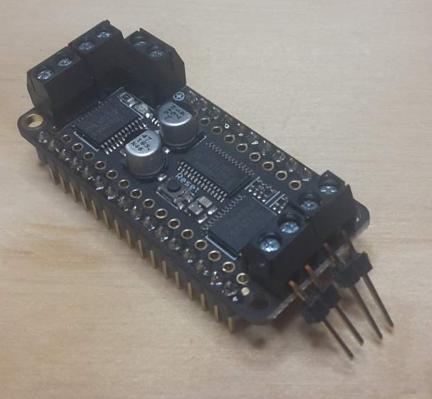
Now we can connect the motors to the header pins:
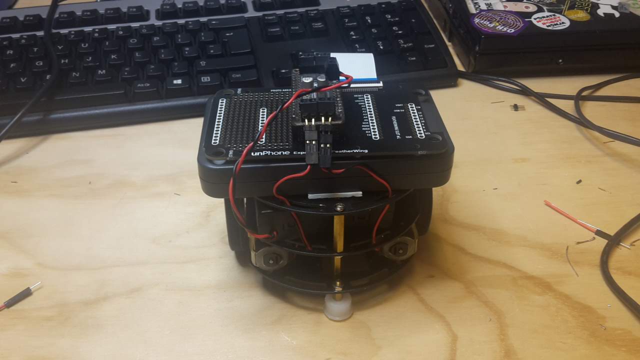
Then screw the battery box wires into the connector at the side of the motor driver – make sure to put the red lead in the + connection and the black one into the – connection:
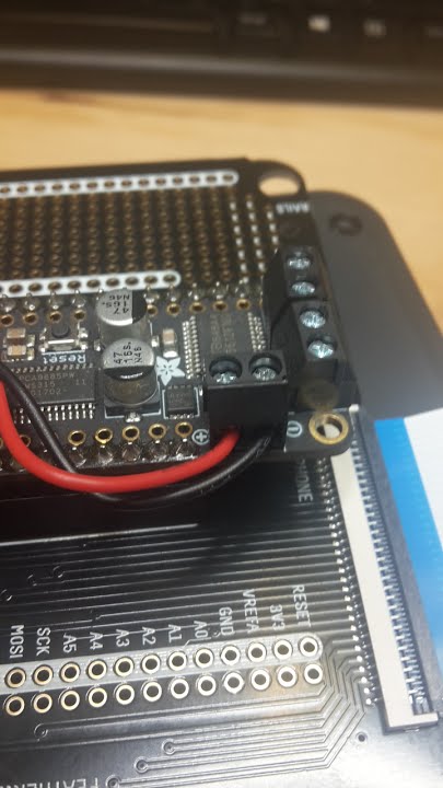
You can follow the next section here: basic code for robot to test out the robot.
We are using the aREST library to provide a RESTful interface – one that responds to HTTP calls to URI’s like //esp32/forward.
The code is on github here and the code is explained on this Adafruit page.
Modify the sketch to use your local wifi access point (phones on tether work well as they report the IP of connected devices). Also change the first two lines to adapt this code to run on the ESP32; they should read:
    #include <WiFi.h>
    #include <aREST.h>
Once you have programmed your ESP32 you can discover it’s IP address either on the serial port or via your hotspot. Using a laptop, join the same network as the ESP32. Edit the script.js file inside the interface directory to replace the IP address with that for your ESP32. Now you can run the demo.html file in a browser for wifi control of the robot!
(This project doesn’t require any additional hardware, using just a bare ESP32, so is a good choice if you’re not interested in the electronics prototyping side of things.)
As we discussed earlier in the course, the resource-constrained nature of IoT devices makes keeping them up-to-date with security patches and new features a significant challenge, and in situations where network connectivity may be interrupted it is common to allocate two or three times the requisite amount of flash memory to store firmware: one for the current version and one to download the next (updated) version into (and sometimes another one to hold a “factory reset” version). This adds a significant cost to the device.
This project is to port an approach to incremental updates that is used to minimise the size of updates in several contexts including Ubuntu’s snap package manager and Google Chrome’s courgette updates process. Incremental updates work by analysing the difference (or delta) between a new version of (in our case) firmware and the previous version, then sending only the list of changes. A client-side routine is then required to check that the change bundle has come down the pipe successfully and if so apply the change list to the firmware image.
This isn’t a new approach; binary diff for software update is quite common. This blog post has a good summary; systems often use bsdiff or xdelta. The disadvantage is that when differencing object files small changes in source can result in huge changes in the binary: “compiled code is full of internal references where some instruction or datum contains the address (or offset) of another instruction or datum.” The Chrome courgette system is particularly interesting however, because it performs a limited decompile of the object code and then analyses the changes between versions with the address changes separated out from instruction-level changes. This can result in a much smaller diff. (Recent versions of Firefox have taken up the same system, I believe.) Chromium (the open source version of Chrome), for example, sometimes achieves a huge reduction in update size using courgette:
- Full update: 10,385,920 bytes
- bsdiff update: 704,512 bytes
- Courgette update: 78,848 bytes
To do this type of update on an ESP32 we would need to:
idf.py to call this generator while creating build/MyFirmware.elf and build/MyFirmware.binThis project is not an easy option, but if successful would be a real contribution to the community :)
As an advanced topic, it would be interesting to consider the possibility of closing the gap between the old world of C++ firmware burn tooling and the new one of drag-and-drop Python or JavaScript script update that has started to be a common development mode for microcontrollers such as the BBC’s Micro:bit or boards supporting CirciutPython or the Espruino JavaScript port (now including the unPhone; see Appendix B. Can we compress binary firmware updates sufficiently to rival the new approaches?
Another issue to consider here is board support for USB OTG: if we can treat the board as a mass storage device then drag-and-drop becomes trivial in most operating systems. This is one of the key differences between the ESP32 and the ESP32S2 / ESP32S3, for example.
Using an IR LED, start by reviewing the TV-B-Gone codes and code inspiration, then read on for how to get started. Make sure you have collected an infra-red reciever: 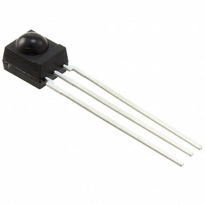 that demodulates the IR transmissions and produces digital signals straight into the ESP32. (You can use these for testing and also to demo the operation of your project in the documentation.)
If we attach infra-red (IR) LED’s to our ESP, we can use it to send remote control commands – for example to turn off TV’s, or perhaps issue a series of commands such as turn on the TV, turn on a satellite box, change the input source, etc.
The mechanics of using the timers is complex and also different on the arduino uno and the ESP32. Luckily the well established IRremote Arduino Library by z3t0 handles this for us. The latest version lists support for ESP32 receiving IR only!
Good old Andreas Spiess has implemented the missing send functionality from the IR remote library.
The libary should be modified to reflect the IR LED pin used on your board – so if you’re installing this yourself then modify the IRremote.h file – line 262 – change: byte timerPwmPin=3; to read: byte timerPwmPin=12; (assuming you’re connecting on pin 12).
In order to know the codes that are used in a certain device (there are hundreds of different propriatary formats!) you can search on the internet – noting that there are at least three ways to write the binary formats and several other ways to express the codes even in a particular protocol.
This page gives good if dense info – combined with this page listing Sony TV device codes.
Ok – so, from the code page, we see that the first table lists basic codes, such as code 21 for power. The Sony:1 at the head of the table tells us that of the various device codes used by Sony TVs, these codes are part of device 1.
So the worked example gives us a template for how to proceed:
Our command is code 21 – convert to the 7 bit binary value 0010101 and reverse it to get 1010100. My device code 1 gets expressed as a 5 bit binary value 00001 and reverse it to get 10000. Put these together to get 101010010000, which is A90 hex. Whew! The 12-bit nature of the codes explains the second parameter in the call.
And looking at the example sketches included with the library, IRsendDemo does indeed use code 0xA90 – this provides confidence that maybe I’ve got my sums right – and lo and behold – it turns my TV off!
It is often easier to connect an IR receiver device: and read the codes that are produced by an existing remote control. In order to do this we use a TSOP4838 photoreceiver device that has a sensor, amplifier, demodulator and signal conditioning circuitry all built in. It connects directly to the ESP32 as illustrated:
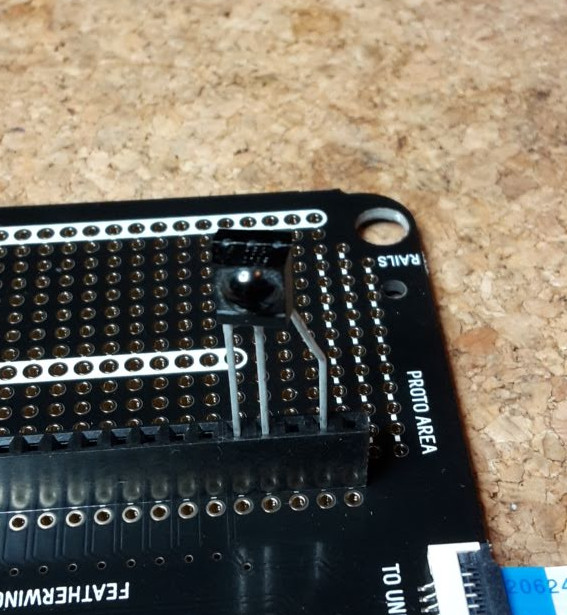
Pin 1 is Data Out, pin 2 is Ground and pin 3 is Vcc – 3.3V in our case. This means you can just put the sensor into the expander as shown above, and the data comes into pin A0 (on this image). (However it isn’t very robust!)
NOTE: on the latest (2019) unPhone, pin A0 won’t work for this purpose; use A1 (next along) instead:
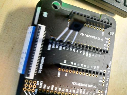
For a more reliable connection, solder the sensor directly into the board (though not on A0!):
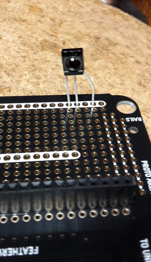
When you have a device that sends IR codes and a receiver that decodes them, you can put them together for testing like this:
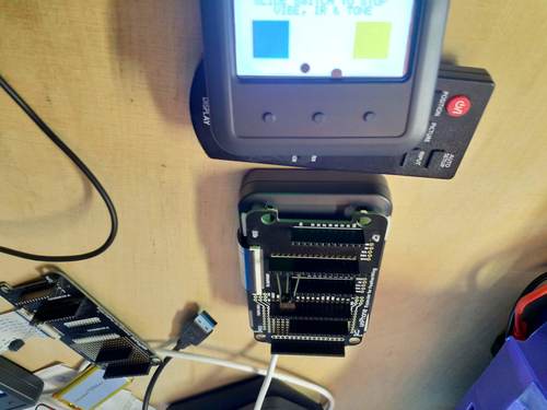
We are using the TSL2591 light sensor in a handy breakout from Adafruit.
You will need to solder some jumper wires to four points on the sensor - these are the same whether you have the square or round board:
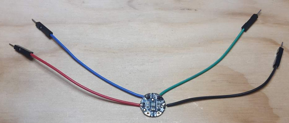
Then it’s a simple matter of plugging the wires into the expander like so:
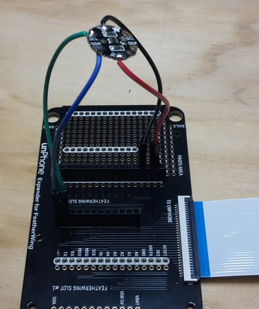
Control the world!!! Or at least, things that plug into a mains socket… This project adds remote mains power switching to your ESP32 using a 433 MHz radio transmitter. This type of transmitter is a common mechanism for remote controls, e.g. for your central heating. The actuator we are using is a radio transmitter circuit that uses the 433MHz frequency:

This is part of the ISM band of frequencies that consumer electronic devices can use without license – in our case we are using electric sockets that switch on and off in response to codes issued on that frequency:

By using a radio-controlled mains socket we cunningly avoid having to interface directly with the mains. Being able to switch a mains powered device such as a light, fan, heater etc. opens up the possibilities of control greatly – hopefully it’s already giving you some ideas…

As you can see from the schematic we can just connect the transmitter without needing any additional components. This transmitter is designed to operate at 5V – but it does work at 3.3V with a lower power consumption but reduced range. If you want to use this transmitter on batteries, you might like to experiment with running it on 5V vs 3.3V and see whether the trade-off is desirable for your project needs.
Soldering the transmitter into the expander should look something like this:
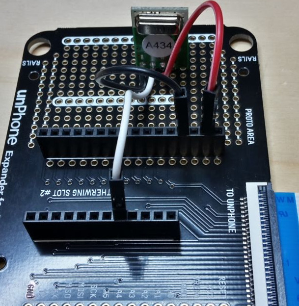
Here I’ve soldered wires into the holes just in front of the ones for the transmitter. On the expander the prototype holes aren’t connected to each other, so on the back I made sure the wires connected to the pins of the transmitter:

The sockets come in packs of three and with a single push button remote control. Eight different sets of codes are used to signal to the sockets so that you can use more than three sockets in one location. The sockets are programmed to match the remote (which can’t be changed), but can also be re-programmed to change the code they respond to. For approx. 3 seconds when power is applied, the socket is in learning mode; if a control code is broadcast during this period the socket will learn this code and begin responding. If no code is received during the first 3 seconds, the socket goes into normal mode and responds to the last code learned. Each socket code has an ‘on’ command and an ‘off’ command – there seems to be no other commands and no feedback – so no ability to read the status of the socket for example.
You can initialise the handy RC Switch library like thus:
#include <RCSwitch.h>
RCSwitch mySwitch = RCSwitch();
Then a couple of setup configurations:
// Transmitter is connected to esp32 Pin #12
mySwitch.enableTransmit();

// We need to set pulse length as it's different from default
mySwitch.setPulseLength(175);
Now we can send a command to the switch:
mySwitch.send(4281651, 24);I’ve mapped out the codes for 10 sets of sockets here: (updated August 2022).
Without an antenna the range of the transmitter is only a meter or so; but a simple aerial can be made with a piece of wire. Using this aerial range can often reach 20-30m and usually can work through walls and ceilings. Instructions can be found here (credit: Ben Schueler).

Once you’ve made your aerial you should solder it so it connects with the pin on the right of the transmitter – marked ‘ANT’ so it will look something like this:
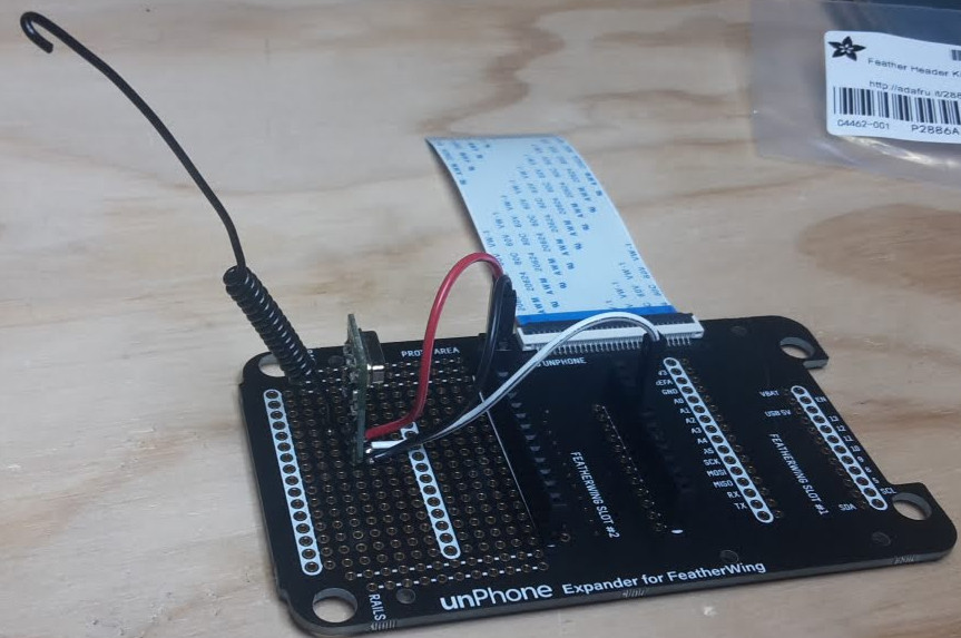
We used to use Adafruit’s I2S microphone breakout board. Figuring out how to wire and drive it is a little tricky but not impossible :)
More recently we’ve been experimenting with Chris Greening’s ICS-43434 mic board. There’s documentation and code from his github here.
Chris Greening’s ESP32-based Alexa-alike uses a custom microphone board:
I wired this up to the Huzzah ESP32 like this:

There’s code to drive it and collect the audio here. Note that the Feather Huzzah pins to connect the mic to are:
.bck_io_num): pin 13.ws_io_num): pin 15.data_in_num): pin 21(Config field .data_out_num is for outward communication on I2S and should be set to I2S_PIN_NO_CHANGE as we’re only listening to the mic in this case.)
To (re-)create the lib/tfmicro tree in MicML follow his instructions here.
Try this:
esp-idf/examples/peripherals/i2s (which is probably in ~/esp if you’ve used magic.sh or the Espressif Linux instructions for setup)Then you can try this to test:
cd ...the-internet-of-things/exercises/MicML
./magic.sh arduino-ide
And open Tools>SerialPlotter.
You should see something like this:

The hardware setup will look something like this (with a white wire for ground, instead of black):


If you hit problems, there’s useful info in this post, and Espressif’s I2S documentation here.
The ESP32 feather can be attached to a featherwing with a VS1053 MP3 decoder chip which can also do a nice job of synthesising MIDI input. Store your .mp3 files on an SD card (after formatting it to FAT), and see the example code for how to play via the headphone jack.
Note that streaming audio is a blocking operation for at least one of the ESP32’s cores, so your UI will have to find clever ways to squeeze into available processing power!
“Show me someone who is bored of LED’s and I will show you someone who is bored of life.” Ahem. This project uses beautiful and useful NeoPixel LEDs to simulate dawn:

Adafruit’s NeoPixels are bright multicolour LEDs controlled via a single signal wire (plus two for power). Read up on them here - we’re using the NeoPixel stick and the NeoPixel Fether.
There used to be a bug with the ESP32 having difficulty with the timing see here, but hopegfully it was fixed here.
To get them working, first solder on three connections for power and data:
Then connect these to the USB 5V, GND and pin A0 as shown:
The challenge with this project is to provide mechanisms to prevent vote stuffing, interception and ensure privacy of votes.
The first thing to do is to use the code for Ex09 so that you have a way to configure your ESP on new networks:
void setup09() { // wifi UI
  ...
}

void loop09() {
  dnsServer.processNextRequest(); // handle DNS  requests
  webServer.handleClient();       // handle HTTP requests
  ...
}Secondly, find the location of your board using Google’s geolocation API. In order to make the things we’re voting on localised, we need a way to find our location and report this.
This could be provided by a GPS chip, however these consume a moderate amount of power and take a fair amount of time to initialise and get a ‘first fix.’ In addition they don’t work well in urban canyons (between buildings) or indoors.
Alternatively we can use a cunning technique that relies on the relative strength of wireless signals. By comparing the signal strength seen by a device with a map of access points the location of the device can be inferred through triangulation.
Google has already done the tedious task of collecting the location of millions of wireless access points and makes an API available (to developers) that takes a list of wireless signals in the location, and returns a latitude and longitude co-ordinate.
Github user @gmag11 has contributed code for the ESP32 that uses the google API to return location data - Google location code
You will need to get a google API key from Google Geolocation API
Note: in order to Get a list of available votes, you could use a Twitter account to store and access votes, using Twitter’s location function, or implement an IFTTT notification mechanism.
This project uses Google’s geolocation API and/or the GPS featherwing to figure out where you are when you press the button.
The idea is to provide a way to signal a “panic” (or need for urgent assistance) to others, e.g. security staff. In order to be a useful panic button, we need a way to find our location and report this.
This could be provided by a GPS chip, however these consume a moderate amount of power and take a fair amount of time to initialise and get a ‘first fix.’ In addition they don’t work well in urban canyons (between buildings) or indoors.
Alternatively we can use a cunning technique that relies on the relative strength of wireless signals. By comparing the signal strength seen by a device with a map of access points the location of the device can be inferred through triangulation.
Google has already done the tedious task of collecting the location of millions of wireless access points and makes an API available (to developers) that takes a list of wireless signals in the location, and returns a latitude and longitude co-ordinate.
Github user @gmag11 has contributed code for the ESP32 that uses the google API to return location data - Google location code.
You will need to get a google API key from Google Geolocation API.
The HC-SR04 ultrasonic sensor is a cheap and cheerful way of sensing distance to solid objects like a wall. The device is well described here: tutorial on ultrasonic sensor.
We can connect it to an ESP32 without needing any additional components:
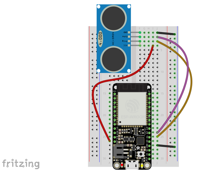 .
.
Following the schematic here:
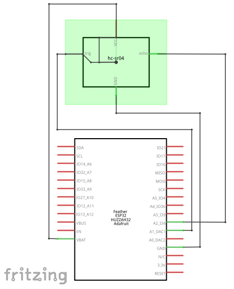 .
.
You can use this sensor without a library, as its operation is so simple. The sensor is triggered by a 10ms pulse to the TRIG pin, from GPIO pin 25. The sensor sends an ultrasonic pulse and waits for the response, triggering the ECHO pin to GPIO pin 34. The time between the trigger and the echo is directly proportional to the distance between the sensor and the object. The sensor doesn’t work properly with small objects and complex fields of view - it’s really designed for detecting obstacles like walls. In code, once the trigger pulse has been set, the arduino function pulseIn is useful to time the response:
int duration = pulseIn(echoPin, HIGH);
int distance = (duration/2) / 29.1;
Serial.print(distance);
Serial.println(" cm");
However, this sensor is not very well behaved! It occasionally gives wrong values, sometimes the pulse never returns to the sensor correctly, and sometimes a spurious signal will be reported. Simple functions to average readings or exclude results that are more than 50% larger or smaller than the average of the last few results can help clean up the data.
(If you want to do a project on this in 2022 you will have to supply your own as we don’t have them in stock.)
The Lilygo T-Watch-2020 is a smart watch development kit based on the ESP32.

The watch includes an accelerometer, touch display, infra-red sensor, loudspeaker and vibration motor. In other words it fits out definition of IoT devices: a networked microcontroller with sensors (accelerometer; touch input) and actuators (screen; vibration motor; the ESP32’s radio). It is powered by a LiPo battery managed by an AXP202 PMU72 and has its own RTC73.
There are many possible projects you can build with the watch, for example:
If you want to emphasise the hardware component of the project, you could also connect the watch to your feather (over WiFi or BT or BLE) and use the feather / LED / etc. combination as an actuator (e.g.: turn the TV on or off over IR when I enter the room), perhaps using a gesture language. In the other direction you might experiment with control of your watch via a mic on your feather, for example.
How to get started? The most comprehensive firmware setup currently available is probably Bill Dudley’s github project, and there is some example shell code illustrating how to set this up in the exercises tree.
There’s a simple predictive text library (see predictor.cpp) in your exercises tree (which was originally written by Mark Hepple – thanks Mark! – and then ported to the ESP32). Currently the UI, using the unphone touchscreen, is very basic – can you improve it? How many words can you support on the ESP without running out of memory?

Using the VS1053’s MIDI synthesis capability and e.g. the ESP’s touch sensors as control mechanisms many musical instruments become possible. Pick up a music player featherwing if you want to build one of these.
Eyes drooping? C programming not seeming quite as exciting as usual? Perhaps you should be getting more sleep :) Can you track your screen-off shut-eye time using a light sensor, and present the data back in an easy to interpret form?
(This requires a pair of ESPs, both with touchscreens, so check that these are available to you before chosing!)
This is a popular game with simple UI requirements, perfect for a connected microcontroller like the ESP32.
These libaries might be worth looking at if you want to do sophisticated UI stuff:
NOTE: we’re retiring this project, partly because it is quite challenging, especially without access to the lab, and partly because there are newer and better solutions that we haven’t had time to integrate into the course as yet. If you’re super confident and really want to give this a go, please get in touch, but if not please choose another project.
The project used three sensors to measure various aspects of Air Quality:
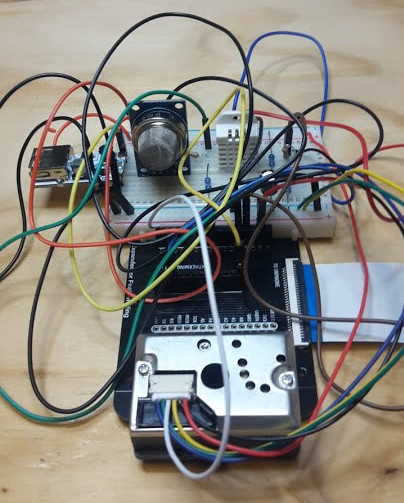
This project is complex to wire up!
The old instructions, for reference:
We’ll be using two low-cost sensors to give an indication of air quality, a dust sensor (Sharp GYP2Y1010AU0F) and a Volatile Organic Compounds sensor (MQ-135). In addition we’re using a digital temperature and humidity sensor, the AM2302, a clone of the popular DHT22.
Both air quality sensors are analog sensors that are powered by 5V. They return a voltage that is between 0V-5V; the level of the voltage is proportional to the level of dust or VOC’s sensed.
Because our ADC (Analog to Digital Converter) in the ESP32 only has a limited input voltage range (0-1.5V with other ranges available) we need to scale the sensor output voltage with a potential divider.
A potential divider is made of two resistors that divide the voltage according to the formula:
Vout = Vin ( R2 / R1+R2 )We need to divide the Vout by 5 to scale it correctly, giving Vout approx 1.3 and Vin=5; working out the equation to fit into the available resistor values is a nice excercise for the reader.
If the reader does not feel like exercising then online calculators, e.g. this one will select resistors that minimise the error.
For further reading about the voltage divider see Sparkfun’s tutorial here.
The output voltages from these dividers go to the ESP32 – it has multiple ADC channels – we are using A2 and A3.
In our circuit, resistors R4 & R5 form a potential divider for the VOC sensor, reducing it’s range from the 0-5V the sensor outputs to 0-1.25V. The ADC has a switchable attenuator and so we can set it for 1.5V range with analogSetPinAttenuation(A0, ADC_2_5db). We’re using this range as it is more linear than the 11db range, but still gives a convenient voltage divider, and we avoid going to the end of the range where the conversion looses accuracy.
For the dust sensor, we can also use the same voltage divider to reduce the 5V output down to a measurable 1.25V, resistors R2 & R3 form this potential divider.
The AM2302 sensor uses a proprietary digital protocol but luckily a library hides that from us. We add a 10K resistor R6 to act as a pull-up on the data signals from this sensor to the microcontroller.
The other components in our circuit, R1 and C1, are needed to make the dust sensor operate correctly. For more information on the dust sensor, read the application note. Note – the capacitor C1 is an electrolytic type that has polarity – make sure you wire it in the correct way round!
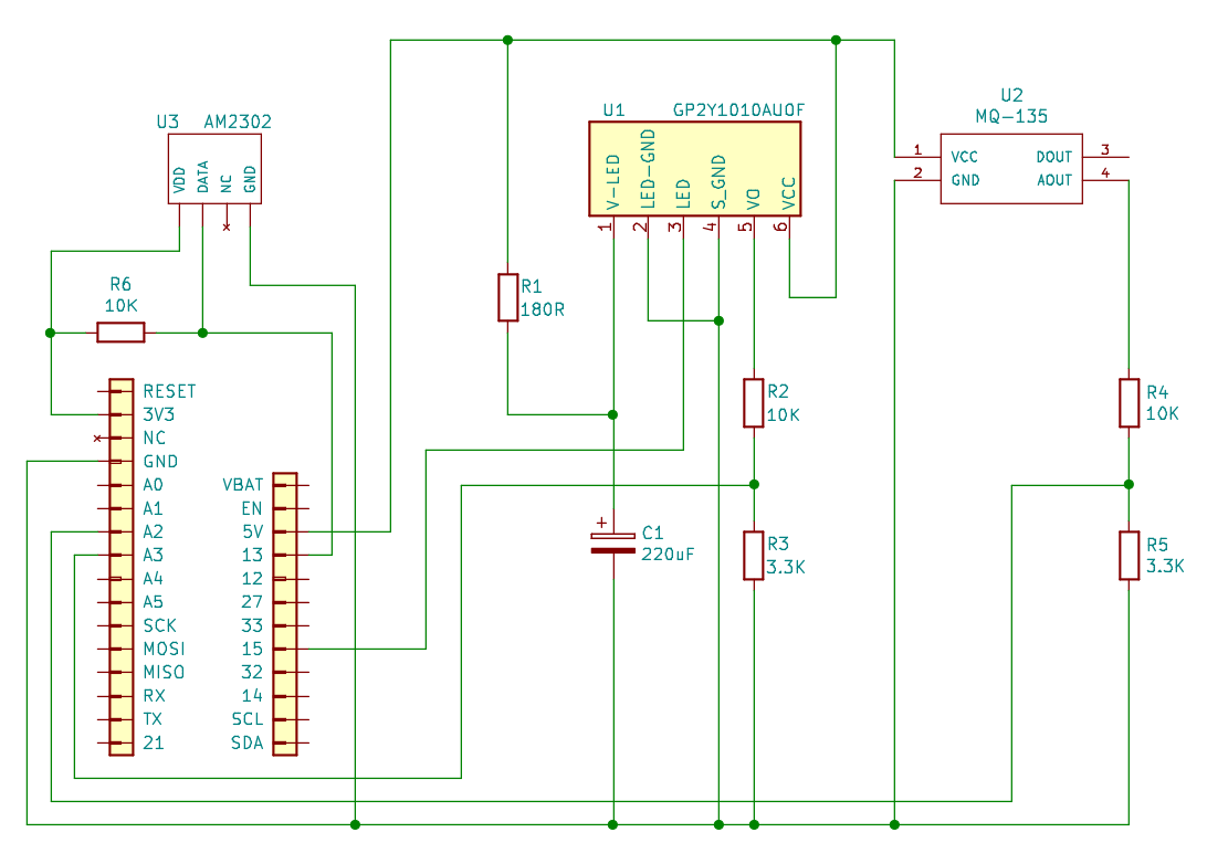
For construction, I recommend using breadboard at first, and then once the circuit is working you can convert it to soldered connections. Stick the breadboard and dust sensors down to the assembled expander board using sticky pads:
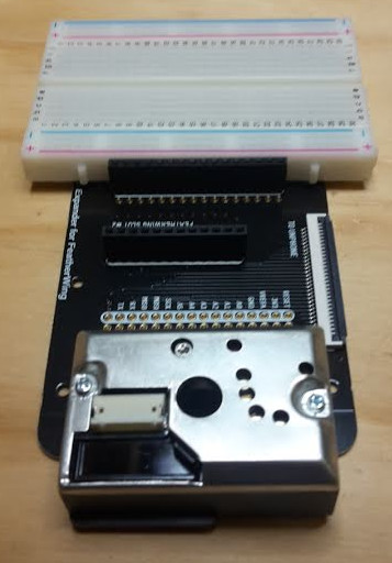
The idea is to place the dust sensor so that the hole in the centre of the sensor is below the board, so that air (and dust) can be measured:
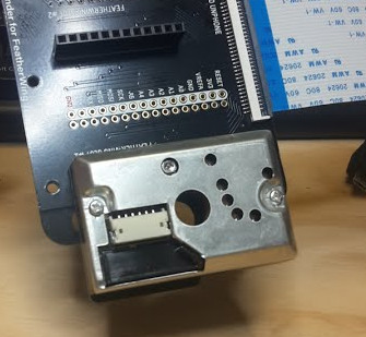
Using the schematic as a guide, connect your component together on the breadboard. You may find the wires from the dust sensor difficult to insert into the breadboard – try twisting the strands of wire together. You may need to use a soldering iron to melt some solder onto the twisted wire – this is called ‘tinning’ the wire:
Then I suggest starting by connecting the power wires – there are three voltages in this circuit, two potential dividers and three signals going into the ESP32! With all those connections it really helps to use colour codes to help keep them all in the right places. I’ve used:
After all the sensors, wires and passive components have been placed on the breadboard it might look something like this:
Seriously – once you have got the circuit working – you are strongly advised to solder the wires neatly in place otherwise you will be spending a lot of time debugging loose wires!
If you’re now using LiPo batteries – please review the safety instructions above and be sure to follow them. If in doubt ask a member of staff.
Our objective this week is to:
Following on from the work we did in the last couple of weeks (on provisioning and over-the-air updates), have a look at these:
If there is a subject with a greater reliance on impenentrable jargon than computing, I have yet to find it. Fog? Edge? (Mist, even?) Since “cloud” has become the accepted term for distributed computing, computation that happens locally has started to acquire its own terminology building on the same metaphor. A smart phone or an IoT device is an edge device (a droplet perhaps, or edge node). The set of edge devices on a network make a fog or mist.75
We start this chapter by putting machine learning and AI in the context of edge devices in the fog. After motivation, the first issue to address is the relatively low power of computational resource available outside of the datacenter, which leads to a discussion of federated learning.
The vast majority of current applications are designed for data processing to be performed predominantly in the cloud. There are several advantages for this model, such as:
But more recently, privacy is becoming a growing concern in the population. Data has long been seen as an important asset by large companies, but only now individuals are starting to recognise this fact about their own data. Streaming data to the cloud may not be the model of future IoT applications.
So what can we do instead to protect data privacy? One answer is to train Machine Learning models at the edge. The method with the most traction in current research is Federated Learning.
Definition:
Federated learning is a machine learning setting where multiple entities (clients) collaborate in solving a machine learning problem, under the coordination of a central server or service provider. Each client’s raw data is stored locally and not exchanged or transferred; instead, focused updates intended for immediate aggregation are used to achieve the learning objective. Focused updates are updates narrowly scoped to contain the minimum information necessary for the specific learning task at hand; aggregation is performed as earlier [sic.] as possible in the service of data minimization … (Kairouz et al. 2019)
In essence, instead of sending your data to the cloud to train an ML model, with Federated Learning the ML model is sent from the server to the edge (on the client). Using the local data of the client, the model is updated to reflect a better performance on the local data. This local update of the model is then sent to the server for aggregation with updates from many other clients. The local data is discarded after the model update and never leaves the device in its raw form.
Federated Learning enhances the following principles:
Federated Learning has been receiving substantial interest recently, both from research and industry, so it’s worth exploring it in the context of IoT data. The underlying conditions for this method to work in the IoT space are that sensing devices (or nearby computing hosted on the local network, e.g. gateways or desktops) have sufficient computing resources to store a fraction of the data and perform the model updates.
In 2016, McMahan et al. introduced FL: “We term our approach Federated Learning, since the learning task is solved by a loose federation of participating devices (which we refer to as clients) which are coordinated by a central server.” (Brendan McMahan et al. 2016) An unbalanced and non-IID (identically and independently distributed) data partitioning across a massive number of unreliable devices with limited communication bandwidth are the best defining set of challenges.
Developing a FL framework:

The steps in training processes:
Typical numbers found in the deployments used at Google’s scale are presented in the table below.
| Scale | |
|---|---|
| Total population size | 106 – 1010 devices |
| Devices selected for one round of training | 50 – 5000 |
| Total devices that participate in training one model | 105 – 107 |
| Number of rounds for model convergence | 500 – 10000 |
| Wall-clock training time | 1 – 10 days |
Google makes extensive use of FL in the Gboard mobile keyboard and in Android Messages. Each time you type on the Gboard and it predicts the word you intend to type next based on the text context, that is used as signal to strengthen the model being used for word prediction. This model is then pulled from your phone and from other users’ phones to update a large global model that is capable of predicting the next word more robustly. Note here, not all the words you type are considered for sharing in the global model, such as usernames or passwords. But anything that falls in the general sense of using the language makes it into the global model.
Apple is using cross-device FL in iOS 13 for applications like the QuickType keyboard and the vocal classifier for “Hey Siri.” The keyboard strategy is very similar to that of Google’s. For the vocal keyword it stores samples that have a lower confidence and did not activate the device. If these are followed by a stronger example that wakes up the device, the immediately previous samples are considered for training and updating the local model.
A growing application of FL is now taking place in medicine and banking, where data is highly confidential, but actors can allow computing to happen in their system closer to the data.
Non-Identical and Independently Distributed (non-IID) phemomena in FL is usually explored in two directions – in hardware and in data:
Two bottlenecks appear in practice:
These bottlenecks can be addressed by compression using quantisation or model reduction:
Federated Learning is a distributed learning setting. This is built on many clients contributing updates to a shared model. A centralised server chooses a set of clients to update the model. These clients update the global model with their own local data and push that back to the server. The server aggregates the updates from the contributing clients and pushes the updated model for many more clients to use (even if they don’t participate in the update).
This course has no lab associated to the theoretical concepts. However, there are many resources online if you want to start playing with FL. The more popular repository is FedML. This has a set of examples and benchmarks you can explore independently. A dedicated implementation for IoT devices is proposed here https://github.com/FedML-AI/FedML-IoT.
Our objective this week is to get cracking on the projects, continuing the course theme of learning by doing. Four more weeks and you’ll have had a real taste of creating a new IoT device, from breadboard to prototype, and be all set to become a practising IoT engineer :)
You should have chosen your project now. If not, do so ASAP!
In section 7.2 I referred to aquaponics, a sustainable intensive agriculture technology. Myself and colleagues work on monitoring and control systems that attempt to make the technology simpler to use, and we build those systems using IoT technology. This section will spend a little bandwidth looking at an IoT system for intensive sustainable agriculture with aquaponics: the WaterElf. First a little context.
Why bother growing things in towns and cities? Most of our agricultural land is already being farmed, and most of our food production is part of a system which prioritises profit over costs like pollution, soil degradation or injustice.
How can we grow more food in more places (and grow it quickly)? My colleague Jill Edmondson ran a project called My Harvest (for which my team in Computer Science built the database backend). Jill’s team used the data from that project (collected from allotment growers across the UK) and a geospatial analysis of Sheffield city green (and grey77) spaces to estimate the amount of food that could be produced within the city boundaries. The results (published in Nature food (J. L. Edmondson et al. 2020)) are surprising: urban spaces have the potential to host large-scale growing that can make a significant contribution to our food supplies.
To do this we need intensive agricultural methods that don’t need soil. Whilst the go-to option there is hydroponics (growing vegetables in disolved fertiliser), the difficulty is that fertilisers are either a scarce natural resource (e.g. potash) or produced using the Haber-Bosch nitrogen fixation process (which is currently responsible for something on the order 1 or 2% of the world’s total energy consumption). The combination of fish and vegetables in a closed loop system — or aquaponics — has both low environmental impact and high productivity.
At Regather’s Club Garden the Institute for Sustainable Food are building an urban farming demonstrator to showcase the potential of the technology, and hopefully to become part of an established urban food hub, on the edge of Sheffield’s https://www.facebook.com/LansdowneEstate/.
Aquaponics replaces the fertilisers used in hydroponic growing with fish food, and uses only as much water as the plants need. It works all year round, and can fit into the nooks and crannies of urban spaces. Vegetarians use ornamental fish; others use edible species.
The technique creates a symbiotic ecosystem of fish and plants that is necessarily clean — if we tried to add fertilisers or pesticides to the growbeds we would soon damage the fish, as would growth factors or prophylactic antibiotics fed to the fish. The widespread use of agrochemicals in our current food production industries drives down resilience — most are dependent on oil, and many inject toxicity into our environment and compromise the long-term sustainability of agriculture. The integrated ecosystem present in aquaponics (combining fish, vegetables, bacteria and worms) results in less disease and faster growth, removing the need for agrochemicals and pharmaceuticals.
The catch? Balancing the ecosystem is tricky, and we don’t know enough about the optimum setups for cooler climates (or about the systems sizes that suit typical UK greenhouses or sheds). Research questions we’re addressing to meet these challenges include:
Connectivity. New-generation microcontrollers like ESP8266 and ESP32 bring a mature wifi stack and modern micro compute resource to the existing Arduino ecosystem, and WiFi is winning the Internet of Things (IoT) connectivity battle in cases where power is easily available. In other cases LoRaWAN, Sigfox, LTE-M and NB-IoT are all candidates vying for uptake. We’re combining WiFi and LoRaWAN, and developing multi-mode device provisioning that will work in both well-resourced, WiFi and power-rich environments and in low resource economies where long range low power radio is more appropriate.
Monitoring. Aquaponics relies on three interdependent sets of organisms (plants, fish and nitrifying bacteria), all of which have to operate within certain parameters. Monitoring water quality (pH, temperature), light levels (lux), and air quality (temperature and humidity), and providing cloud-based data recording for produce outputs, can make managing this balancing act easier and bring the technology in reach of many more users.
Control. The bacterial populations that we rely on for converting ammonia to nitrates thrive in some types of hydroponic growth media that are highly oxygenated, and the resultant combination of nitrate concentrations and oxygen also promote high plant growth rates. A good way to create that type of environment is ebb and flow (or flood and drain) irrigation, which requires solenoid control of growth bed water flows. Industrial solenoids are expensive; we’re experimenting with several cheaper valves appropriate to low resource environments and driving them via MOSFET circuits. We also control lighting, air and water pumps using a 433 MHz transmitter and COTS (commodity) mains switching devices which are widely available (and therefore remove the need to deal with mains voltages in our circuitry).
Analytics. Our connected devices interface with the new generation of IoT cloudside logging, visualisation, event generation, platform integration and analytics (for example on Adafruit.io or IFTTT), along with lower-level data logging on AWS-based cloud VMs that offer high-reliability (EBS) multiregion data storage. An example dashboard:
At the heart of the approach is an IoT device called the WaterElf, which pairs an ESP32 microcontroller with environmental sensing (for lux, air and water temperature, humidity and water levels) and water flow control. The device is open hardware supported by open source firmware on the unphone gitlab repository. An example schematic:

WaterElf is an ESP32-based control, monitoring and communications device for aquaponics. It combines several features characteristic of different greenhouse control systems and water quality monitors used in aquaculture and hydroponics. The latest version of the WaterElf features wireless sensors to measure pH, light intensity (LUX), water temperature, air temperature and humidity as well as three ultrasonic sensors that enable the monitoring of water levels in three growbeds from a single device. A programme controlling the opening and closing of valves, thereby regulating water levels, runs locally in the Elf. The timing of this is controlled by the water level (high water levels sending a signal to stop the flow) – if for any reason this signal does not come, filling of tanks will automatically stop after 15 minutes to prevent overflow.
Saving the world with fish poo plus electronics. You heard it here first :)
Our objectives this week are to:
As noted in an earlier chapter, Adafruit’s “All the IoT” series has lots of useful background on IoT connectivity options. Hera are the Adafruit-hosted copies: - episode 1, transports - episode 2, protocols - episode 3, services - episode 4, Adafruit.io - episode 5, security
More details on application-layer communication protocols:
Cautionary tales:
Phones. They’re miraculous! Maps, cameras, streaming this that and the other… and they even make phone calls. But: they use up scarce minerals (that are often mined in peril). The server clouds they connect to use thousands of times more energy than bitcoin. And they steal our attention, leak our data, compromise our privacy. Perhaps we don’t need a miracle in our pockets every minute of the day? Sheffield’s unPhone IoT platform isn’t a phone alternative but it has the potential to replace some of the sledgehammers we currently crack nuts with (and it can be a way to keep more of your data under your own control).

For students of the IoT, for makers and developers of novel devices, the unPhone provides a rapid prototyping environment, made easier by the pre-integrated UI, PMU83, accelerometer, LoRa radio and etc., with an expansion capability conforming to Adafruit’s FeatherWing standard. Having prototyped a device on the unPhone, the resultant circuit constitutes a stand-alone unit appropriate for productisation by competent fabricators. The board is manufactured by Pimoroni in Sheffield UK, in partnership with the University of Sheffield.
(If the target hardware doesn’t include a screen etc., the unPhone-based prototype can be trivially transferred to the relevant Feather microcontroller board (e.g. the ESP32S3 feather using the expander board’s Feather-compatible sockets. The screen is typically very useful during the development process to reduce reliance on the serial lines for debug output and the like.)
Extensive documentation and integration with the Arduino, Espressif and PlatformIO open source communities make getting up and running fast and lightweight. The device can be programmed in C / C++ or CircuitPython.
The systems have also been the foundation of IoT courses for more than 1000 people so far at the University of Sheffield, and at a more general level the work helps:
Several research programmes are supported by the work, including tracks in IoT devices for monitoring and control of aquaponics systems (Coleman 2014; Hamish Cunningham and Kotzen 2015) (supported by a cloud-based data aggregation and analytics infrastructure (Tablan et al. 2013) orginally developed as part of the GATE architecture (H. Cunningham, Gaizauskas, and Wilks 1995; Hamish Cunningham et al. 2002)). The hardware has contributed to projects including the Urban Flows Observatory (Munir et al. 2019), the Pitch-In Connecting IoT Capabilities project (Czekster et al. 2021), the unPrism and Vigil Auntie projects (Al-Mhabis and Cunningham 2017; Rudd and Cunningham 2021a, 2021b, 2022) and the MYHarvest urban agriculture database (J. Edmondson et al. 2019; J. L. Edmondson et al. 2020). The COM3505 Internet of Things level 3 undergraduate course enters its 8th iteration in Spring 2025.
This chapter tours the hardware and firmware programming environment of the unPhone. (See Chapter 7 for the story of how we developed the device.) We focus here on the device hardware (next section), the programming model, its power consumption characteristics and the details of the circuitry it is built on. We finish with a note on versions.
Lets begin with an overview of the various things that are part of the unPhone and how they are connected to the microcontroller at the centre of it.
The unPhone has a USB C socket, that provides both power and a serial line connection. When you connect power the on-board battery will automatically begin charging. When the USB is unplugged the battery will switch over and power the unPhone. And if you plug your unPhone into a computer, you can program it and interact with it.
The RGB LED can display 7 different colours, made by switching on or off each of the red, green or blue parts. If you switch all three on at once, you get white; if you mix red and blue you get purple, and mixing red and green gives yellow. There’s also a red charging LED underneath the USB socket, which is on when the battery is being charged.
The reset button is connected to the microcontroller’s reset circuit - this will always reboot the device. It’s set into the end so you’ll need a pencil or paperclip or etc. to press it.
The micro SD card slot can be read by the microcontroller. It has a push-push type socket where the card goes into the slot, and out again by pushing it in gently.
The IR (infra-red) LED isn’t visible, but sends remote control codes to TV’s, hi-fi’s etc. You can use this to turn off annoying TV’s nearby, for example!
The on/off slide switch turns the unPhone off and on. Even when turned off, the battery will still charge if USB is plugged in. And you can control this yourself in your programs, to make the unPhone wake up even when it’s turned off. This is useful if you want to save battery power and wake up every few minutes to check something, for example.
The three push buttons above the screen have a tactile feeling, so they can be operated in your pocket.
As well as the usual Wi-Fi and Bluetooth radios, the unPhone has an ultra-low power long range radio that uses the LoRa European frequency (868 MHz). It’s compatible with The Things Network LoRaWAN system, with gateways all round the world (including Sheffield!). This radio has many hundreds of meters of range, probably more, but a very low bandwidth. So you can’t stream music, let alone video. But you can send and recieve messages, alerts, sensor readings etc.
The gyroscope sensor gives accurate measurements of the movements of the unPhone. It can be used for various things such as a step counter, a spirit level or gesture control (e.g. change screens on an interface when the unPhone is tilted).
The vibration motor gives a gentle buzz that is barely audible but can be felt, suitable for notifications or alarms.
Touchscreen gives a bright clear display with 640x480 pixels; and the touch pressure can be felt, so a drawing program can draw a thin line with light pressure and a thicker line with more pressure for example.
The built-in battery has a capacity of 1400 mAh - so will power the unPhone for around 6 hours or so, with the screen on and using WiFi or LoRaWAN heavily. The screen backlight is the most power hungry item, so if you can program a sleep mode that turns it off, you can easily double the battery life. Using the radio’s less will also reduce power consumption.
And if you want to connect two Adafruit Featherwing expansion boards, and / or add some more components to the unPhone, you can use the expansion shield. It exposes all the normal Feather pins so you can just plug in your chosen Featherwing and go!
This section describes the C++ programming model of the unPhone using several example applications. For the latest code, build environment recommendations and troubleshooting tips see the library’s GitLab repository. (To program in CircuitPython see Appendix B.)
Before we begin it is worth remembering the number one truism about the IoT and about devices based on microcontrollers: they’re small! The game is to make them as small as they can be while still performing their intended task. (This is quite different from general purpose computing, where we try to build devices that are appropriate for any computational task, or at least any task which doesn’t require distributed computing to succeed.) The pressure to be as small as possible in the IoT means programming machines that are very like computers were several decades ago, and we often end up using programming idioms and tools that are similarly venerable. So: the terrain is rough, there’s not much space for acrobatics and we’ve only our wits to sustain us :)
Which is a long-winded way of saying:
In common with the ESP32 family and many other microcontrollers, sensors and actuators the unPhone is supported by an Arduino library that provides a hardware abstraction packaged as a C++ class that follows certain conventions. Its declaration starts like this:
class unPhone {
public:
  unPhone();                              // construction
  unPhone(const char *);                  // construction with app name
  static unPhone *me; // access singleton in static context after constr
  void begin();                           // initialise hardware
...
These first methods deal with creating an unPhone object (with an optional application name), accessing that object from static contexts (after construction, via the me member variable), and initialising the hardware (with the begin method).
The unPhone class is intended to be singleton, i.e. we should only ever construct one object of the type. (There’s only one piece of hardware running the firmware instance, after all!)
The most common way to create an application for the unPhone is to write an Arduino sketch that instantiates the unPhone class. Several examples of this are available in the library’s examples/ directory. The simplest is called minimal:
#include "unPhone.h"                      // pull in class definition
unPhone u = unPhone("minimal");           // construct an unPhone object
void cycleLeds();                         // helpers to cycle RGB LED...
void printLEDPins();                      // ...and debug print the pins

void setup() { // the Arduino code calls this once /////////////////////
  Serial.begin(115200);                   // enable serial printing
  D("\nin setup(), doing unPhone begin()...\n\n") // say hello in serial
  printLEDPins();                         // print out LED pindefs
  u.begin();                              // initialise unPhone hardware
  u.backlight(false);                     // no UI: turn backlight off
  D("\ndone with setup()\n\n")
}

void loop() { // the Arduino code calls this in an infinite loop ///////
  u.ir(false); cycleLeds();               // cycle through RGB, no IR
  u.ir(true);  cycleLeds();               // cycle through RGB, IR on
  u.ir(false);
  D("\nrepeat\n")                         // once more from the top...
}
...
We construct an unPhone object called u, initialise the serial line (for debug statements) and print out some diagnostic information. (The D macro behaves like C’s printf function, and can be excluded from the build by defining UNPHONE_PRODUCTION_BUILD as a compile flag.)
The call to u.begin() sets up everything that we need to operate the device, from the I²C bus to the SD card. It also creates FreeRTOS tasks that take care of power management, LoRa radio, factory test mode and UI event servicing.
(The library includes UI zero which is a simple GUI built on Adafruit’s excellent GFX. It can be turned off by setting an UNPHONE_UI0=0 compile flag, and this is done in minimal. The setup() method finishes by turning off the LCD backlight as is isn’t needed when there is no UI running.)
The loop() method cycles through the various colour options of the RGB LEDs, while also toggling the IR LEDs.
This is pretty much the simplest illustration of how to program the unPhone. Below we’ll look at more interesting examples, but first let’s explore the unPhone class a little more.
After a couple of utility methods, the class declaration continues like this:
uint8_t version();                          // hardware revision
const char *getMAC();                       // the ESP MAC address

// pindefs for version 7 omitted; version 9+ pindefs:
static const uint8_t LCD_RESET        = 46;
static const uint8_t BACKLIGHT        =  2 | 0x40; // 0x40 = on TCA9555
static const uint8_t LCD_CS           = 48; // CS = SPI chip select
static const uint8_t LCD_DC           = 47; // DC = data or command
static const uint8_t LORA_CS          = 44;
static const uint8_t LORA_RESET       = 42;
static const uint8_t TOUCH_CS         = 38;
static const uint8_t LED_RED          = 13;
static const uint8_t POWER_SWITCH     = 18;
static const uint8_t SD_CS            = 43;
static const uint8_t BUTTON1          = 45; // left button
static const uint8_t BUTTON2          =  0; // middle button
static const uint8_t BUTTON3          = 21; // right button
static const uint8_t IR_LEDS          = 12; // the IR LED pins
static const uint8_t EXPANDER_POWER   =  0 | 0x40; // enables exp brd

static const uint8_t VIBE             =  7 | 0x40;
static const uint8_t LED_GREEN        =  9 | 0x40;
static const uint8_t LED_BLUE         = 13 | 0x40;
static const uint8_t USB_VSENSE       = 14 | 0x40;
This long list of constants gives pin definitions that map from the ESP32’s connections to the various peripherals that are wired up to it. For example, the power switch is connected (in version 9) to GPIO 18 on the ESP32S3 microcontroller. (Pins that are OR’d with 0x40 set bit 7 high, and are used when talking to peripherals that are connected to the unPhone’s TCA9555 chip – see below.) To accomplish simple tasks like turning the GREEN LED on, we can use digitalWrite(unPhone::LED_GREEN, HIGH), for example, though note that the class provides shortcut methods for this type of task. They’re mostly self-explanatory:
bool button1();              // register...
bool button2();              // ...button...
bool button3();              // ...presses

void vibe(bool);             // vibe motor on or off
void ir(bool);               // IR LEDs on or off
void rgb(uint8_t red, uint8_t green, uint8_t blue); // RGB LED
The RGB LED is controlled via the rgb(int, int, int) method. For example rgb(1, 0, 0) will light the red LED, rgb(0, 1, 0) the green, and so on.
The methods related to power are used to implement powerSwitchTask(), which is scheduled by FreeRTOS to manage power states (next section).
bool powerSwitchIsOn();      // is power switch turned on?
bool usbPowerConnected();    // is USB power connected?
void checkPowerSwitch();     // if pwr switch off, shut down
void turnPeripheralsOff();   // shut down periphs
void wakeOnPowerSwitch();    // wake interrupt on pwr switch
void printWakeupReason(); // what woke us up?If the compile flag UNPHONE_UI0 == 1 then the UI controller class can be accessed via the uiCont member, and redrawing and event servicing performed with the redraw() and uiLoop() methods:
void *uiCont;                // the UI controller
void redraw();               // redraw the UI
void provisioned();          // call when provisioning done
void uiLoop();               // allow the UI to run
void recoverI2C(); // deal with I2C hangsThe display and touchscreen hardware are accessed via the tftp and tsp pointer members (TFT stands for thin-film transistor, which in this case is the type of LCD display the unPhone contains). The accelerometer is available at accelp and should be queried with the getAccelEvent method.
// the touch screen, display and accelerometer /////////////
Adafruit_HX8357 *tftp;       // UI0 uses Adafruit LCD lib
XPT2046_Touchscreen *tsp;
Adafruit_LSM6DS3TRC *accelp;
void getAccelEvent(sensors_event_t *);     // accelerometer
void backlight(bool);        // backlight on or off
void expanderPower(bool);    // expander board power on/off
An example of using the accelerometer is provided in unPhoneLibrary/examples/everything, a sketch that exercises almost all of the device’s capabilities. The accelerometer allows us to determine the unPhone’s physical orientation; Gareth used it to program an Etch-a-Sketch game:

The method for querying the accelerometer works by passing through a pointer to a sensor_event_t type, which is defined by the Adafruit Unified Sensor library. This is a common idiom in memory-constrained C and C++ programming, where the caller of a method that returns non-trivial data first allocates the memory to store that data and then passes its address through to be written into. For example, from the UI0 implementation as used in the everything sketch:
  sensors_event_t event;     // allocate memory for accel reading
  up->getAccelEvent(&event); // get the reading (up: unphone ptr)
  // now we can get x, y, z etc. from the reading:
  if(event.acceleration.x    ...
Details of the sensor_event_t data type are available here. (Aren’t Adafruit wonderful?!)
The SD card is acesssible via the sdp member
SdFat *sdp; // SD card filesystemThe unPhone’s LoRa radio module can be used to send short messages over long distances. A FreeRTOS task (unLoopTask) that services LoRa transactions is fired up by unPhone::begin(), which uses the loraSetup() and loraLoop() methods, after which messaging is available via loraSend, which behaves like printf. For example, from the everything sketch:
u.loraSend("UNPHONE_SPIN=%d MAC=%s", UNPHONE_SPIN, u.getMAC());This will send a message to The Things Network something like this UNPHONE_SPIN=9 MAC=7CDFA1FDFCE4. The maximum length of the interpolated string payload is defined by unPhone::LORA_PAYLOAD_LEN and should not be exceeded.
// LoRa radio
void loraSetup();                           // init the LoRa board
void loraLoop();                            // service lora transactions
void loraSend(const char *, ...);           // send TTN LoRaWAN message
static const uint8_t LORA_PAYLOAD_LEN = 101;// max payload bytes (+ '\0')Power management is a complex task! The work is taken care of in powerSwitchTask; see next section for the gorey details. The pindefs for the power management chip (known variously as PMU, BMU or just BM84) and associated API are as follows:
// power management chip API
static const byte BM_I2CADD   = 0x6b; // the chip lives here on I²C
static const byte BM_WATCHDOG = 0x05; // charge end/timer cntrl register
static const byte BM_OPCON    = 0x07; // misc operation control reg
static const byte BM_STATUS   = 0x08; // system status reg
static const byte BM_VERSION  = 0x0a; // vendor/part/revision status reg
float batteryVoltage();               // get the battery voltage
void setShipping(bool value);         // tells BM chip to shut down
void setRegister(byte address, byte reg, byte value); //
byte getRegister(byte address, byte reg);             // I²C...
void write8(byte address, byte reg, byte value);      // ...helpers
byte read8(byte address, byte reg);                   //
Of these only batteryVoltage() is likely to be useful for most unPhone programmers.
We quite often want to store small amounts of data to persist between invocations of our firmware, and the unPhone class finishes with a little API to facilitate this, built on top of the Preferences API:
// a small, rotating, persistent store  (using Preferences API)
void beginStore();                    // set up store area
void store(const char *);             // save a value
void printStore();                    // play back list of strings
void clearStore();                    // clear (doesn't empty nvs!)
static const uint8_t STORE_SIZE = 10; // max strings; must be <=255/2

// misc utilities
const char *appName;                  // name for the firmware
const char *buildTime;                // build date
...
In the everything example we use it like this:
u.store(u.buildTime); // remember firmware build date
...
u.printStore();       // print out stored messages
(The unPhone library also stores details of power states and wakeup reasons, which will also be printed by printStore here.)
As well as class unPhone we have class unPhoneTCA, which models the device’s TCA9555 IO expansion chip that is controlled over I2C and to which the SPI chip select (CS), reset and etc. lines of many of the modules were connected in versions before spin 9. From 9+ only the LEDs, expander board power and the vibration motor are on the TCA. To use these connections the IO expander has to be told to trigger those lines. This meant that the available libraries for the modules also needed to be adapted to talk to the TCA, e.g. when doing digitalWrite or pinMode. We did this by injecting code to call our own versions of these functions (defined below) and setting the second highest bit of the pin number high to signal those pins that are controlled via the TCA9555. In later versions we don’t need to patch the libraries any more, as only our own code is talking to the TCA. In any case, the unPhoneTCA class manages the chip. (It used to be called IOExpander but was renamed to prevent confusing it with the unPhone expansion board, an additional PCB that connects to the main board by ribbon cable.)
class unPhoneTCA {
  public:
    static const uint8_t i2c_address = 0x26; // the TCA9555's I²C addr
    static uint16_t directions;    // cache current state of ports...
    static uint16_t output_states; // ...after read during init
    static void begin();
    static void pinMode(uint8_t pin, uint8_t mode);
    static void digitalWrite(uint8_t pin, uint8_t value);
    static uint8_t digitalRead(uint8_t pin);
...
};Lastly, there are a couple of convenience macros for printing to serial and for calling delay for particular periods:
// macros for debug (and error) log/printf, and delay/yield/timing
#ifdef UNPHONE_PRODUCTION_BUILD
# define D(args...) (void)0;
#else
# define D(args...) printf(args);
#endif
#define  E(args...) printf("ERROR: " args);
static const char *TAG = "MAIN";        // ESP logger debug tag
#define WAIT_A_SEC   vTaskDelay(    1000/portTICK_PERIOD_MS); // 1 sec
#define WAIT_SECS(n) vTaskDelay((n*1000)/portTICK_PERIOD_MS); // n secs
#define WAIT_MS(n) vTaskDelay( n/portTICK_PERIOD_MS); // n milliThe unPhone library includes UI zero a simple example user interface built on Adafruit’s GFX (graphics) and implemented in unPhoneUI0.h and unPhoneUI0.cpp. To enable it, set a UNPHONE_UI0=1 compile flag. The everything example, referred to above uses UI0 and is a good source of usage examples.
An alternative to GFX, with a much richer (and more complex) set of UI elements, is LVGL, a Light and Versatile Graphics Library. The examples/lvgl sketch runs an very impressive LVGL demo that looks like this (without the pointer and a bit slower!):

On the unPhone:

(Note that this doesn’t run on unPhone 7 unfortunately, too big to fit!)
In UI zero we display an arrow on each screen that can be used to navigate between different elements of the interface. The menu of different screens looks like this:

To add a new screen to the UI and the menu, take these steps:
unPhoneUI0.h:
enum ui_modes_t { ..., ui_mynewelement, ... }UIElement, e.g. class MyNewUIElement: public UIElement { ...unPhoneUI0.cpp:
NUM_UI_ELEMENTS by oneui_mode_names, e.g. “My new UI screen” and add this to modeName(), e.g. case ui_mynewelement: return "ui_mynewelement"; break;allocateUIElement(), e.g. case ui_testrig: m_element = new MyNewUIElement(up->tftp, up->tsp, up->sdp); break;UIElement subclass, e.g. void MyNewUIElement::draw() { ...;This should now appear on the UI zero menu screen. (For a detailed example, see this commit.
One of the design goals for almost all IoT devices is to minimise power consumption. The unPhone’s consumption ranges from around 50 microwatts (µW) when hibernating up to a typical runtime of around 500 milliwatts (mW). For comparison, Pete Warden summarises typical smartphone runtimes (following (Tarkoma et al. 2014)) as in the thousands of milliwatts (mW)85.
The unPhone includes a battery and power management unit (PMU) with integral LiPo charging and several different power states that controlled using the on/off slider switch at the end (which is “on” when slid closest to the nearest edge of the case and “off” when nearest to the center).
When the device is ON all internal functions are available, and the device will draw power from USB if available or battery if not.
When the device is turned off, there are three states:
Power draw in these different states is approximately as follows (measured at Uni Sheffield using an INA219 Featherwing, an EEVBlog mCurrent Gold, and again using an N27GG bench PSU; we further verified the figures using an IDS1054B scope at Pimoroni):
(When working with the expansion board, note that its power supply must be enabled in software: unPhone::expanderPower(true).)

The diagram above shows six states that the unPhone can be in, depending on the position of the power switch, whether USB power is connected or not, and also whether the user code has chosen for the unPhone to sleep or not.
Although the top four states are different in that the battery is either being charged or drained during them, they are also similar in that your code runs in exactly the same way in both the sleep states and running states. The battery charging is managed entirely by the PMU (Power Management Unit - the BQ24295 chip in the unPhone) and doesn’t require any programming to support it’s operation.
The arrows on the diagram show what actions can be taken, and which power state the unPhone will be in if that action is taken. If you want to change two things at once, sorry, you can’t! You have to do one change and then another - the unPhone’s clock ticks at 240 million times a second - so even if you think you have unplugged the USB at exactly the same time as switching the power switch - in reality you won’t be able to get them that close!
Let’s say we start with the power switch in the ON position, and USB power connected. We will press the reset button so that we know things are starting at the beginning of our code.
The unPhone is now in the Running state at the left of the diagram. The battery is charging - or if it is already fully charged, then it’s kept fully charged.
Suppose we now disconnect the USB cable, and the power that comes along it. We follow the Unplug USB arrow and see that we are still in the Running state - only now the battery is draining to power the unPhone. We don’t have to pay attention to this, because the PMU handles the switchover from USB power to battery power for us. If you want to find out which of the Running states we are in, you can do that by using the function usbPowerConnected() like this:
if (unPhone::usbPowerConnected() == true) {
  Serial.print("We are connected to USB and charging the battery");
} else {
  Serial.print("We are not connected to USB and draining the battery");
}
Now we are running on battery power, we might want to save some power and sleep for a while. That way instead of running at full power for a few hours, we can sleep for a bit, wake up, do something, then sleep again. We can run for weeks or months that way – because sleeping uses only a tiny amount of power. We can go to sleep using the built in function esp_sleep_enable_ext0_wakeup(). When we use this function, we must tell it how we want to be woken up – otherwise we will sleep forever! We can use it like this:
esp_sleep_enable_ext0_wakeup(unPhone::BUTTON1, 1);
esp_deep_sleep_start();
In the first line, we are calling the sleep_enable function, and setting the wake-up to be when we press button 1(the left button). The 1 at the end says that we want to be woken up when the switch is pressed.
The second command, esp_deep_sleep_start(); will immediately make the unPhone will enter a sleeping state. Because we are still disconnected from USB, the battery is powering the unPhone - but whilst sleeping it will last for weeks. The chip is powered down and isn’t running code, connecting to wifi or anything else (but see below for subtleties!).
You can see that from this state, there are three possible arrows that show which states we can go to next. We can wake up from sleep by pressing button 1 - in which case our code will start running from the next line after we went to sleep.
At an implementation level, the key method is unPhone::checkPowerSwitch method, which does this:
if power switch off
    turnOffPeripherals

    if USB power off
        go to shipping mode
    else
        enable wakeup on power switch
        enable wakeup on 60 second timer
        go to deep sleep
The method is called like this:
checkPowerSwitch (so that if the power switch is off, and e.g. we’ve woken up because of a timer call or because USB power has been connected, we can go straight back to either sleep or shipping)checkPowerSwitchcheckPowerSwitch will then choose deep sleep or shipping appropriately based on whether USB power is connectedThis means that when the device boots with the switch off, due to the transition out of shipping when USB is (newly) connected, our call to checkPowerSwitch will put it into deep sleep.
In addition we wake from deep sleep periodically in order to check that USB is still connected, and if not, then move to shipping mode (so that we minimise battery draw when charging isn’t available).
This means that with the switch off we are always in either deep sleep or shipping mode, except for momentary transitions caused by USB connect / disconnect.
The charge LED indicates status like this:
| battery connected | USB connected | charge LED |
|---|---|---|
| yes | yes | on if charging |
| yes | no | off |
| no | yes | flickers |
This section describes the various elements of the unPhone, with reference to the unPhone9 hardware schematics (PDF; individual page images appear below).
NOTE: the next section describes unphone 6v2, but the general principles and many of the specifics also apply to later versions. (More details on versions are below.)
The unPhone device has an ESP32 microcontroller at the centre, so let’s start our look at the schematic there. The ESP32 is the large block on the left side:

In addition to all the GPIO pins connected to various other chips, there are some ‘housekeeping’ type connections as well. Rather than drawing long lines all around the schematic connections are labled and you have to remember that pins with the same label are connected together. Naturally the ESP32 has power pins to give it 3.3V 3V3 and ground GND. It also has a set of six pins that connect to the flash memory, and another pair that connect to the USB serial. There is a reset pin RESET that has a small capacitor linked to it to give a small delay to ensure the chip starts up cleanly. There are a pair of transistors also connected to the reset and GPIO0 lines, linked to the programming pins used when burning firmware onto the ESP32. This ensures that the chip can be put into programming mode and reset afterwards to boot normally.
The USB to serial chip used is a CP2104, shown on the lower right hand side, which provides a USB interface on one side for your computer, and a UART connection together with control of the reset and programming pins of the ESP32 on the other. It allows for serial communications in both directions during normal operation, and the uploading of new firmware in programming mode. The CP2104 needs a couple of capacitors near the chip to help provide a steady power supply. (As many chips switch very quickly, they can create electrical noise on the power supply wires. As a result, most if not all chips have a capacitor or two very close to them, to decouple this noise from other parts of the circuit.)
The LoraWAN radio module on the lower left hand side is the RFM95W – and this connects to the ESP32 using the SPI bus together with a couple of additional GPIO lines. These extra lines allow the radio to signal when it has data to be received. Again, the radio module has a decoupling capacitor, and because it’s a radio module, a connection for an antenna. Cunning board design from the Pimoroni people means this antenna fits beautifully into a little cut-out at the top of the board.
The accelerometer and gyroscope chip is an interesting device and the way we’ve used it is also unusual. Two similar chips are shown on the schematic at the top and centre, the LSM9DS1 or the LSM303DLHC. Only one of these chips is actually fitted during manufacture, and they both connect using I2C and have the usual decoupling capacitors.
(Whilst building the device, we discovered that the LSM303DLHC sensor we had been using was becoming obsolete. The rate of development in these MEMS sensors in particular has been very rapid over the last few years, so a part that was brand new and exciting in 2013 is replaced by cheaper and better alternatives five years later. Pimoroni were able to source some of the remaining parts of the older model, but as insurance they also designed a place on the PCB to take the alternative part. That way, the same circuit board could be used with either sensor.)
The I2C expander at the top right of the schematic is an I2C device that provides additional GPIO pins – in our case we are using the TCA9555 which gives us 16 additional GPIO pins. An interupt pin is also provided, and connected to the ESP32 to allow us to respond (even waking up from deep sleep) when a device connected to the expander changes state. The expander is connected in turn to:
TFT_RST and backlight BACKLIGHT_ENLEDR, LEDG, LEDBLORA_RSTLCD_CSLORA_CSTOUCH_CSSD_CSalso connected to the expander are: - one of the three buttons SWITCH1 - the power switch POWER_SWITCH_BUFFERED - a connection to the usb power USB_VSEN_BUFFERED
The final three expander GPIO’s are used to set the version – in this way the same codebase can be used on the ESP32 and by interrogating the value of the three version bits we can programmatically tell which version of the unPhone we are running on.
Like many I2C devices, it has some address pins which can be connected to ground or 3.3V to set the I2C address of the device. In this case we are setting pin A0 to ground and pins A1 and A2 to 3.3V – which sets the device address to be 0x24 (24 in hexadecimal – 36 in decimal).
A couple of additional devices are shown on the first page of the schematic - the vibration motor and the Infra-red LED’s. They are both high-current devices and so they are connected to the ESP32 via a MOSFET switch. This is a transistor that takes a tiny signal voltage and switches a much larger current – the ESP32 can’t supply much current directly. There is also a snubber diode across the vibration motor as it is a coil and generates high voltages when suddenly disconnected. The snubber diode provides a discharge path if high voltages build up in the motor coil and protect the MOSFET.

On page 2 of the schematic we have the screen and associated driver circuitry (the HX8357) – the screen is connected with SPI as it needs relatively high data rates. The touch sensor that’s integrated at the front of the LCD uses the STMPE610 driver with it’s own SPI connection to the ESP32 – and so needs it’s own Chip Select connection. In addition the SD card socket is connected to SPI – you can see that no additional components are required – an SD or micro-SD card connects directly to the SPI bus.
The backlight chip generates the higher voltage needed for the white leds behind the touchscreen – and is triggered by the BACKLIGHT_EN signal. The backlight chip handles generating the 20 or so volts from the 3.3V provided to it – and also provides a constant current to the backlight to make sure the LED’s are well lit but don’t burn out.

The final page 3 of the schematic shows some power management chips, a buck voltage converter which takes the 5V and generates 3.3V and a buffer chip to ensure that voltages higher than 3.3V don’t go to the ESP32. We are using a BQ24295 battery management chip to manage the LIPO battery as this is a critical function and also has safety implications. (Pimoroni have extensive experience with this chip and it has been proven in practice in diverse applications.) The BQ24295 connects to the ESP32 using I2C and can report on the state of the battery, any error conditions and how much power can be drawn using USB. It can also be instructed to enter ‘shipping mode’ which completely disconnects the battery from the circuit to prevent the battery discharging during shipping. We are using it to minimise power draw – an ultra deep sleep.
There have been nine prototypes so far (of which only 7 and 9 are current as of late 2022):
This document describes spin 9, the first retail version.
Our objective this week and next is to finish, commit and push the project work. Good luck!
There are two dishes on the dessert menu.
First, as is frequently noted in the literature, you can’t say “IoT” without mentioning the network, and we’ll fill in one of the blanks in our earlier discussions of connectivity by summarising the more common examples of off-board communications protocols.
Second, we promised right back in Chapter 1 to return to the subject of hope, and so we will do.
We build our things using local protocols (or buses) to integrate their sensors and actuators (e.g. UART, SPI, I2C) — we saw examples of these in chapter 5. We get our things connected using network transports, and get them talking to each other (or to gateways or to the cloud) using network protocols.
Adafruit’s IoT video series (see section 10.3) is excellent on transports (and their key criteria of “power, distance and bits”), including:
Transports deliver bits between devices, and between devices and gateways or devices and the cloud. Transports are like the telegraph, or smoke signals: they pass along data, but without imposing an interpretation on that data. Protocols sit on top of transports; we can think of them as the language that devices use to speak to each other (a bit like morse code, or “three puffs means the Vikings are coming!”). The rest of this section looks at off-board (or non-local) networking options for the IoT, and finishes with a look at LPWAN options.
So far we’ve used: HTTP(S) over WiFi. Other important options exist at the application layer (and LPWAN is important):
HTTP, and REST (a set of conventions plus JSON or XML on top of HTTP), is probably the most popular protocol (see below). The big three non-HTTP protocols are:

More recently web sockets have become an options, lower overhead than HTTP but also lower level).
Important differences include the security models (often not baked in to the earlier protocols, later layered on with SSL/TLS), QoS, levels of support:
Their relative popularity was summarised by an Eclipse Foundation survey:

The rest of this section concentrates on Lower Power Wide Area Networks (LPWAN) IoT connectivity options, and especialy LoRaWAN and The Things Network.
WiFi is popular, but it is designed for high bandwidth devices, which may be quite wasteful in this context (our IoT gizmos are probably not going to be streaming HD video!). Because of this a variety of LPWAN options are coming that more closely mirror IoT specificities (very low data rates, low power radio options). The leading examples:
One solution to all this choice is the ‘throw in the kitchen sink’ approach — e.g. Pycom supporting 5 networks.
The LoRa (Long Range) radio protocol is a (physical layer), spread spectrum (~125 kHz) protocol employing a frequency-modulated (FM) chirp. LoRaWAN is a media access control (MAC) protocol (network layer) layered on top of LoRa. Upload / download are symmetrical. More details in Andreas Spiess’ video:
LoRaWAN has come to particular prominence recently because of the success of the Things Network. This crowdfunded LoRaWAN initiative enables distributed LoRaWAN has been very successful in spreading across the world, based on its democratising manifesto:
Everything that carries power will be connected to Internet eventually. Controlling the network that makes this possible means controlling the world. We believe that this power should not be restricted to a few people, companies or nations. Instead this should be distributed over as many people as possible without the possibility to be taken away by anyone.
There are two main families of alternative to LoRaWAN: UNB (e.g. Sigfox) and the new cellular offerings (LTE-M and NB-IOT). Ultra Narrow Band (UNB) uses less spectrum than LoRa, and experiences lower noise (interference) levels as a result. Upload / download are asymmetrical (download, or network to device, is lower bandwidth than upload, or device to network). Both Sigfox and NB IoT use UNB.
Sigfox is a global LPWAN network operator that: tries to build adoption at the device (hardware) level by minimising connections costs; makes money by selling bandwidth; competes with current mobile telecoms providers. NB IoT and LTE-M are from the big telecoms companies.
The mobile operators (working together as 3GPP) have made several responses to LPWAN competition:
The key criteria are bandwidth vs. range and vs. power:

(The other protocols: mentionned are: ZigBee, but this is more about PANs (personal area networks) than WANs; BlueTooth and BlueTooth LE, ditto. These make sense as device-to-gateway protocols, and if we assume that the gateway has mains power, then it is likely to use WiFi or wired ethernet.)

This has been a whistle-stop tour of IoT network transports and protocols.
On day one of the fourth iteration of the IoT course from which these notes originated (last year), I had the unexpected and slightly unsettling pleasure of inviting one hundred (mostly) strangers into my bedroom (mediated, of course, by our Zoom-alike video conferencing tool) for my first lecture of 2021. The forward view from my Sheffield home was of more lockdown, more illness, more poverty, and less of the pleasures of human company that sustain and nourish us as members of our miraculously social and cooperative species. There had to be, I thought, some silver linings hiding in this vast and ugly grey cloud. There were three that I came up with then.
First, chaos is the new normal. Don’t worry if you’re blown off course. Don’t stress about that code that doesn’t compile. We’re only human, and the world is a difficult place to live. Try your best to keep smiling, expect others to sympathise and they probably will, and make sure to have a silly hat ready to hand at all times.
Second, like banging your head against a wall, it will feel really good when it stops!90
We’ll get to the third in a minute, but I’ve since thought of a fourth silver lining, which is how well the need to isolate to protect each other has proved our respect and love for our fellow strugglers. Most especially the wonderful extent to which the young and strong and healthy have carefully isolated and distanced in order to protect others from infection. Everyone is a hero, and you are all beautiful.
The one that I’d like to delve into here, though, was silver lining #3, viz.: it is more obvious than ever that our social systems are profoundly broken, and that the old ways don’t work. Those ways are what got us into this nightmare in the first place! So we have to build back differently. I’ll finish this section by summarising a little of why that has to be true (which is all a bit of a downer; feel free to skip ahead!) and then share a few glints of optimism, a few shards of hope, poking their bright beams through the overcast. And hope there is; so heads up!
(Skip to the next section if you’re feeling low!)
The pandemic, climate change, a decade of austerity ended by a massive spree for corrupt procurement: we are not, my friends, floating gently along the River of Contentment. As noted by Peter Wadhams in his Farewell to Ice (Wadhams 2017),
…the existing level of carbon dioxide in the atmosphere is sufficient to cause unacceptable amounts of warming in the future. We no longer have a ‘carbon budget’ that we can burn through before feeling worried that we have caused massive climate change. We have burned through the budget and are causing the change now. … By now it is too late. The CO₂ levels in the atmosphere are already so high that when their warming potential is realized in a few decades, the resulting temperature rise will be catastrophic. (p. 192)
What to do? The first thing is to recognise that the problems are neither the accidental consequence of imperfect electoral systems nor the outcome of unpleasant character or greedy individuals. Not to say that these things don’t exist and aren’t significant at any particular point in time, but they are not the causes of the underlying tendency towards disaster that we are, unfortunately, firmly routed on.
No, the problems are systemic, and structural.
Lord Stern, who was commissioned by the UK government in the mid-naughties to study The Economics of Climate Change (Stern and UK, Treasury 2007) advocated aiming for a likely 3 degree temperature rise as being “economically viable,” and rejected all other options as non-viable. The report then included all sorts of evidence that shows the 3 degree rise to be a huge gamble, with odds of 50:50 in some cases of much worse consequences.
In other words, as set out by Stern at the behest of the UK Treasury, our economic system cannot support odds better than the toss of a coin for avoiding catastrophic change. Can we conclude anything other than that the economic system itself is at fault? And the situation has only worsenned since then. If it is not economically viable to save the planet, then the economic system is wrong.
It is common to think that markets find efficient solutions. They don’t: they find profitable solutions. And our markets are dominated by a quite small number of truly humungous corporations, vying to become even larger. In a 2011 article on the Network of Global Corporate Control, complex systems specialists from a Swiss university (Vitali, Glattfelder, and Battiston 2011) analysed “the relationships between 43,000 transnational corporations” and “identified a relatively small group of companies, mainly banks, with disproportionate power over the global economy” (New Scientist, October 2011). The study “combines the mathematics long used to model natural systems with comprehensive corporate data to map ownership among the world’s transnational corporations (TNCs)” and uses data on “37 million companies and investors” with details of “all 43,060 TNCs.” The research “revealed a core of 1318 companies” that “represented 20 per cent of global operating revenues” and “the majority of the world’s large blue chip and manufacturing firms — the ‘real’ economy — representing a further 60 per cent of global revenues.” Further, “it found much of it tracked back to a ‘super-entity’ of 147 even more tightly knit companies … that controlled 40 per cent of the total wealth … Most were financial institutions. The top 20 included Barclays Bank, JPMorgan Chase & Co, and The Goldman Sachs Group.” In other words, 150 or so organisations (mostly banks) control the lion’s share of world production. Another 1000 or so control much of the rest.
One thing that the markets dominated by these huge corporations do often drive is competition. (Not all the time: when the banks cease to be competitive the state bails them out; when a powerful group of companies stitches up one sector then they’ll inflate prices. But as a general rule, markets are competitive arenas.) Competition in our economy means that each company has to grow (or else your competitor will get big enough to buy you or undercut you or otherwise get their hands on your share of the pie). Infinite growth is built in to the fundamental model of our economy. Of course there are, in reality, limits to growth: common sense can tell you all you need to know here, but if that doesn’t cut it then get a few of your friends or colleagues to rendezvous in the bathroom or the stationary cupboard and then just keep on packing them in. Economists may tell you that ‘externalities’ mean that growth is unlimited, but your friends will tell you that things are getting pretty stuffy already and to please stop being such a dozy wazzock. As globalisation has spread corporate competition across the world, so growth gets less and less viable within existing markets.
Competition also means that if one corporation or country manages to drive down the wages and social services of their workforce then they automatically put pressure on their competitors to do the same. Otherwise the higher profits of the cheapskates will let them encroach on the markets of the higher paying. Over time this creates a race to the bottom.
And all this destructive chaos is the basis of our food system, and the zoonotic melting pots that it has created; as Wallace wrote presciently in 2016, “Highly capitalized agriculture may be farming pathogens as much as chickens or corn” (Wallace 2016).
So much, so depressing. Bleugh.
It is sometimes said that the only certainties in life are death and taxes. I think we can safely add a third certainty: change. The systemic tendencies (towards infinite growth or minimal wages) which we can see working themselves out in our food system (progenitor of the covid pandemic91) or our environment (and the melting ice caps) or our health systems (where PPE stocks became an afterthought) create a structure which is both massively dynamic and permanently unstable. I think that if we raise our heads and look far enough ahead, even as we judder and shake atop this swirling cauldron there is every chance that we can steer a course to a more rational world, and save ourselves from the whirlpool at the center.
Why? Three reasons.92
The net revolutionised the virtual world and made publishing free to all. But what about the chair your sit on or the fork you eat with? What if we get the ability to share, modify and build anything, in the same way we can publish anything? What if we can democratise the creation and recreation of the physical world? What if we can devolve manufacturing to individuals and communities? Perhaps we would make different choices? Perhaps we wouldn’t put profit before people?
If the last 20 years were about the web, then the next 20 will be about making. Why? Ubiquitous connectivity and decentralised production in the virtual world have made revolutions in creating, sharing and consuming on-line. Now the same changes are starting in the world of manufacturing, and the consequences are likely to be massive.
Remember how hard it used to be to publish? Photocopiers spawned a whole generation of fliers and fanzines, but the big-time of global distribution used to be a very closed world. When we publish we share, and the web has let us share as never before – but, until recently, we’ve mostly used the web to share information (in the form of bit streams of one sort or another). The next revolutionary wave of technology brings the ability to share into the physical world – it brings the information revolution from bits to atoms. And as Chris Anderson writes in his Makers93 the physical world dwarfs the virtual. (There’s perhaps an 80-20 ratio between economic activity devoted to atoms in comparison to bits.)
Capitalism drives innovation, which brings with it continual waves of technological revolution.94
Anderson’s book quotes Cory Doctorow saying that increasingly “the money on the table is like krill” – many many tiny chunks of nutrition that suits a new type of sieve, smaller and more distributed (a “long tail”). Both authors imagine the changes that will take place when the means of production become minituarised, localised, and – in a sense – democratised. At least under some circumstances the small and the open and the fast moving can sneak beneath the corporate radar long enough to become viable alternatives – like my friends at Pimoroni in Sheffield, for example, who sold tens of thousands of locally-made boxes for the Raspberry Pi.
The new methods of manufacturing (CAD-CAM designs driving CNC routers, 3D printing and laser cutting), and the new culture of open source and dynamic virtual organisations start to challenge corporate dominance, at least around the edges. China’s explosive growth and its willingness to ignore the west’s definition of “intellectual property” helps too (though bringing with it the labour relations of the sweatshop).
Anderson talks of a “future where the Maker Movement is more about self-sufficiency… than it is about building businesses….” This, he says, is “closer to the original ideas of the Homebrew Computing Club or the Whole Earth Catalogue. The idea, then, was not to create big companies, but rather to free ourselves from big companies” (pp. 225-226)
We can also make a link into the argument for localist economics made by organisations like the Transition Network (e.g. in Rob Hopkins’ books) – peak oil, social instability and environmental crisis all point to the local and the small scale as a key source of sustainability and resilience. The more stuff we can manufacture within short distances of where we live, the safer we are (not to mention the saved carbon in long-distance transport).
Welcome to the future – perhaps it will be of our own making :-)
Industry was pumping private data into its clouds like the hydrocarbon barons had pumped CO₂ into the atmosphere. Like those fossil fuel billionaires, the barons of the surveillance economy had a vested interest in sowing confusion about whether and how all this was going to bite us in the ass. By the time climate change can no longer be denied, it’ll be too late: we’ll have pumped too much CO₂ into the sky to stop the seas from swallowing the world; by the time the datapocalypse is obvious even to people whose paychecks depended on denying it, it would be too late. Any data you collect will probably leak, any data you retain will definitely leak, and we’re putting data-collection capability into fucking lightbulbs now. It’s way too late to decarbonize the surveillance economy. Cory Doctorow, Attack Surface (Doctorow 2020)
Cloud computing has driven miraculous reductions in the difficulty of large scale data collection, analysis and distribution. This has allowed us to conquer many previouly insoluble problems, and, to a degree, democratised access to massively scaleable computation. It has also had two more negative consequences. In the context of the market-driven imperative to sell the next plastic widget to ever more passive and isolated consumers, advertising has become the rationale for a surveillance system more pervasive and all-encompassing than the worst dystopian nightmares or our forebears. (As part of the same process, the carbon footprint of the global datacenter has reached a significant fraction of our total energy uses, including a troubling quantity of energy devoted to blockchains95.)
And then there’s the spies. Half a dozen years ago I wrote:
If you’ve been paying more than a gnat’s hair’s width of attention to All Things Internet in the past year or so, you’ll know that the US and the UK have been spending the odd spare billion of taxpayers’ hard-earned on a programme of indiscriminate surveillance of everything you, I and the dog do on-line.
(This is fine of course. I’ve nothing to hide. You’re welcome to pop round and put a microphone in my toilet and a webcam in my bedroom — though I may demand the right to fit the same gear in your house first… That ok? And I reserve the right to point out that a couple of hundred thousand people have the same access to all your data that Edward Snowden had shortly before he walked out of a US government building in Hawaii with several gigabytes of leak. If he can do it, how many others? And do you trust them all? You do? Great! Now, please email your credit card numbers and a selection of explicit selfies to me. It’s for your own good, honest.)
The spies like to cultivate back doors in the cryptography that protects on-line transactions. Even if that was ok, there’s no way to have a backdoor that only a spy can use. Four years ago, in the wake of a massive attack on UK medical computing, I wrote that:
The ransomware cyber attack on the NHS is horrifying — and as a computer scientist I feel ashamed that the world my field helped create is now at the mercy of such destructive scammers. It didn’t have to be this way!
This note looks at the context of the attack — why did the NSA help the attackers?! — and explains the “kill switch” and how it slowed the spread of the WannaCry worm. It concludes with ways we can avoid this type of nightmare in the future.
First, the spooks: the NSA (and GCHQ) believe that they need (and have the right) to see every piece of digital communication made by any citizen at any time under any circumstances. More than that — they also believe that they’re entitled to turn on your computer or phone or TV and listen on its microphone or watch on its camera. (That’s why Facebook’s Mark Zuckerberg tapes over his laptop’s webcam!)
There’s a problem: just as we don’t leave home without locking our doors, we don’t leave our computer systems unguarded. How are the spies to cope? They do two things:
“Persuade” software companies to leave deliberate holes in their security. (This is a little like convincing all lock installers to post a copy of every key to the local constabulary, only worse: digital keys are much easier to copy or steal. When Amber Rudd says WhatsApp needs a handy backdoor for law enforcement purposes, this is what she means!)
Break into computer systems, subvert their security mechanisms and suck up the data from your email, chats, documents, etc. etc.
This second activity is what has helped bring the NHS’s computer systems to their knees. One of the NSA’s programs for breaking into Microsoft software (codenamed Eternalblue) was stolen and publicly released in April. The black hat hackers behind WannaCry adapted it to their own nefarious purposes, and we’re now suffering the results.
Government not only supports the spies in these efforts, they allow them to do their worst in total secrecy, even in the courts. In the UK we’re now banned by the Investigatory Powers Act from hearing in court about what evidence was collected in this way and how — giving a whole range of government agencies and employees carte blanche to compromise our online security with impunity.
Since then the Solar Winds hack has demonstrated even more powerfully how vulnerable this process (and the closed-source software that makes it possible) makes us all. Open source is part of the answer, but the situation is urgent; what to do?
Tim Berners-Lee’s answer, from his company Inrupt, is the Solid project to decentralise personal data storage. With a longer pedigree, Freedombox has been building personal servers to move the basic functions of cloud-based SaaS into our homes. Hook these up with the IoT, with programmable personal devices and open systems, and we’re starting to see ways to claw back our data: to build our own fog from our domestic gateways and personal IoT devices.
There’s another potential upside here, to do with prospects for deconvergence, disaggregation, and device respecialisation. Sherry Turkle’s fantastic but terrifying book Alone Together explains how “Technology has become the architect of our intimacies. Online, we fall prey to the illusion of companionship, gathering thousands of Twitter and Facebook friends, and confusing tweets and wall posts with authentic communication. But this relentless connection leads to a deep solitude.” The mental health penalties of this contradiction are increasingly commonplace, especially amongst the young, our digital natives.
The project I would like to do is about making it easier not to look at my phone so often (and about sharing less of my personal data with the internet behemoths). We have spent a decade squeezing all the information processing functionality in our lives into a single device (and a marvellous device it has become: smartphones aren’t going away any time soon). My problem is that whenever I decide to step away from the beast for a little while (to get a break from all the messaging, for example, or rest my eyes on a paper book for a change) one of the other functions of the phone calls me back almost immediately (I want to put some music on, or check a recipe, or etc. etc. etc.). What I would like is to separate out some of those functions into special-purpose devices: informational appliances that are more restricted, less all-encompassing. This is partly what smarthome gadgets like Echo or HomePod or Nest attempt to do, but at the cost of sending yet more data to the cloud (and from there to identity thieves, or, whenever it feels the need, to the state – see above).
In this context I’m excited by the possibilities of connected microcontrollers like the ESP32, which are low energy and low cost enough to be used in volume, but powerful enough to do useful things in a smartwatch package like this one, for example. IoT devices exist at the edge of the cloud. If they become more peer-to-peer, more foggy, (and if we include the substantial computate power now available on the gateway ARM processors96) then we can reduce reliance on the cloud.
So: informational device disagreggation! New privacy in the fog! Unlimited free biscuits for all nerds! You heard it here first.
When not seen through the distorted lens of their supposed efficiency, markets are destructive. Instead we need to think of efficiency as what best meets human needs. This means that:
…“what’s good is what’s good for the biosphere.” In light of that principle, many efficiencies are quickly seen to be profoundly destructive, and many inefficiencies can now be understood as unintentionally salvational. Robustness and resilience are in general inefficient; but they are robust, they are resilient. And we need that by design. Kim Stanley Robinson, The Ministry for the Future (Robinson 2020)
Resilience is the ability to bounce back from stresses, strains and shocks. A society is resilient if it can supply its needs (e.g. for food, shelter or health) without relying on systems outside of its control. A society is not resilient if it relies on shipping large parts of its needs half way around the world. We are vulnerable to disruption brought by war, or the chaotic weather systems brought by climate change, or the volatile price of oil.
The Transition Network make a strong case for the benefits of working towards community resilience, not least because the act of making positive change, even when that change is necessarily partial and incomplete, is a great way to enjoy life! Connecting to our locality, to the people around us, is a great way to feel genuine togetherness and to reduce our reliance on the virtual variety analysed by Turkle. And the spin-offs are to make us all stronger: for example, increasing local food production can help us adapt to change and make our communities more resilient.
There’s lots to do! Dive in!
…the strongest, in the existence of any social species, are those who are the most social. In human terms, most ethical… There is no strength to be gained from hurting one another. Only weakness. (Ursula le Guin, The Dispossessed)
Ok, I’m not very good at counting (that’s perhaps why I’ve spent most of my working life with computers; they do the numbers!). There are more than three reasons for hope; almost uncountable reasons, and the main one is you!
Thanks for coming out to play, and best of luck with your journey! Let’s leave the last word to our old mate Albert, who knew a thing or two…
A human being is a part of this whole, called by us “Universe,” a part limited in time and space. He experiences himself, his thoughts and feelings as something separated from the rest — a kind of optical delusion of consciousness. This delusion is a kind of prison for us, restricting us to our personal desires and to apportion for a few persons nearest to us. Our task must be to free ourselves from this prison by widening our circle of compassion to embrace all living creatures and the whole of nature in its beauty. (Albert Einstein.)
Our objective this week is to finish, commit and push the project work. Good luck, and bon voyage!
This chapter contains material on build systems and build issues (e.g. timing) that are beyond the scope of the course. They are of varying relevance; use them as advanced background if you wish, but note that they may not work as expected!
References to the magic.sh script below refer to a version which is now present as old-magic.sh.
This section describes setting up an ESP-IDF CLI build. The instructions are for a Raspberry Pi running the Debian Buster port (which used to be known as Raspbian but now seems to have mutated into RaspiOS97). The instructions should work pretty much unchanged on Ubuntu 20.04. (If you are on other platforms you’ll need to adapt the instructions or use a VM or docker – see next section.)
If you need a cheap machine to develop for the IoT, Raspberry Pi models 4 or 400 are both capable of doing the job. They won’t be the fastest environment, but for around £/$/€100 you can get a capable computer that will plug into your TV or HDMI monitor and do everything you need to for the course. (A good choice would be this kit, for example, or this one.)
Below I describe how to get up and running with ESP32 development on the Pi. Note that the setup process took several hours (on a fast network), so don’t leave it until 10 minutes before your deadline :) (The complete setup uses around 2.5GB of the flash disk, depending on configuration.)
Here’s some more timing information, for install and build (using the firmware and scripts in the HelloWorld example, which will be introduced later):
magic.sh setup
magic.sh idf-py build
main only) using magic.sh idf-py build
Note that although setup and clean compiles are slow on the Pi, the compile/burn/test cycle is reasonably quick at under 30 seconds. This means that you can work productively on a Raspberry Pi, so long as you allow an hour for the initial setup. (This is from the command line, of course; running a big IDE like VS Code or Eclipse would no doubt be slower!)
To set up the operating system:
~/.ssh/authorized_keys and turn off password login in/etc/ssh/sshd_config by adding PasswordAuthentication noTo get the ESP32 development environments running:
latest: the most recent available, instructions herestable: the last release, instructions hereFor example, using a pre-release IDF 4.3 in December 2020:
sudo apt-get install git wget flex bison gperf python3 python3-pip python3-setuptools cmake ninja-build ccache libffi-dev libssl-dev dfu-utilpython3 the default:sudo update-alternatives --install /usr/bin/python python /usr/bin/python3 10mkdir ~/espcd ~/espgit clone --recursive https://github.com/espressif/esp-idf.gitgit clone --recursive https://github.com/espressif/arduino-esp32.gitcd esp-idfgit submodule update --init --recursivegit checkout --recurse-submodules 357a27760cd ../arduino-esp32;git submodule update --init --recursivegit checkout --recurse-submodules 41e392f6698cd ~/esp/esp-idf./install.shecho "PATH=$PATH:~/.local/bin; export PATH" >>~/.bashrcecho "alias get_idf='. $HOME/esp/esp-idf/export.sh'" >>~/.bashrcget_idf to set up or refresh the SDK in any terminal session; check that this is working:
get_idfwhich idf.py: this should report something like/home/pi/esp/esp-idf/tools/idf.pyTo try burning an example:
cd; cp -a esp/esp-idf/examples/get-started/hello_world .cd hello_world; idf.py build flash monitorWell done! Please give yourself a pat on the back. If you’re feeling brave: VSCode for the Pi is available here :)
If you don’t have an Ubuntu or RasbiOS environment available, you can try using docker (although you won’t be able to burn firmware directly unless you’re on another Linux platform).
If you’ve cloned the course repo (the-internet-of-things) and cd’d into it, and connected an ESP32 to USB, you should now be able to do the following:
sudo docker build . -t 20.04:magicsudo docker run --device=/dev/ttyUSB0 -it 20.04:magiccd the-internet-of-things/exercises/HelloWorld/./magic.sh idf-py build (or just ./magic.sh on Linux, which will also do the burn and monitor serial)(Command-line syntax for docker on non-Linux platforms may also be a little different; see the docker docs.)
If you’re on Linux, and you have the correct device specified (/dev/ttyUSB0, for example), then you should also be able to burn the firmware, e.g. by just doing ./magic.sh. This won’t work on MacOS or Windoze because no easy way to map the serial port driver model currenly exists In this case you’ll need to copy the the-internet-of-things/exercises/HelloWorld/build/HelloWorld.bin file out of your container and burn the firmware using a local install of ESP-IDF (which somewhat defeats the object!). If you want to try this, the command that is needed to burn the firmware can be copied from the output of the docker build, e.g.:
...
Generated /home/ubuntu/the-internet-of-things/exercises/HelloWorld/build/HelloWorld.bin
[1081/1082] cd /root/esp/esp-idf/components/esptool_py && /usr/bin/cmake -D IDF_PATH="/root/esp/esp-idf" -D ESPTOOLPY="/root/.espressif/python_en...D WORKING_DIRECTORY="/home/ubuntu/the-internet-of-things/exercises/HelloWorld/build" -P /root/esp/esp-idf/components/esptool_py/run_esptool.cmake
esptool.py --chip esp32 -p /dev/ttyUSB0 -b 921600 --before=default_reset --after=hard_reset write_flash --flash_mode dio --flash_freq 40m --flash_size 4MB 0x8000 partition_table/partition-table.bin 0x16000 ota_data_initial.bin 0x1000 bootloader/bootloader.bin 0x20000 HelloWorld.bin
esptool.py v3.0-dev
Serial port /dev/ttyUSB0
Connecting......A new kid on the block for ESP32 development support is the ESP-IDF VSCode plugin: see the installation guide for details. The plugin is still pretty new, and the process of getting it to work with a clone of both the IDF and the Arduino core is pretty involved. When it works, though, it looks like a nice environment to use :)
I got it to work like this (on Ubuntu 20.04):
sudo apt-get install python3-venvsnap install --classic code on Ubuntu)magic.sh setup)source ~/.espressif/python_env/idf4.3_py3.8_env/bin/activatesource ~/esp/esp-idf/export.shcodeCntrl+Pext install espressif.esp-idf-extension~/.espressif/python_env/idf4.3_py3.8_env/bin/python -m pip install -r~/.vscode/extensions/espressif.esp-idf-extension-0.5.1/ esp_debug_adapter/requirements.txtPATH, OPENOCD_SCRIPTS and python, e.g.~/.espressif/python_env/idf4.3_py3.8_env/bin/pythoncode the-internet-of-things/exercises/HelloWorldbuild/flash/monitor button on the bottom barSee also: Quick User Guide for the ESP-IDF VS Code Extension.
This section is about using VSCode in a more basic, but still useful mode.
Some more tweaks may need to be done for full IntelliSense compatibility, so you may need to hide squigglies until we figure out the additional paths you need to add. You can still use these instructions to do things like uploading your code to the ESP32, though.
First install VSCode itself; on Ubuntu you can do that like this on recent versions:
snap install code --classicYou can then run the beast from the command line with code, or from the launcher by vs....
Now install the C++ and Arduino extensions:
~/.config/Code/User/settings.json on Linux systems:
libraries directory under that oneE.g.:
"arduino.path": "/.../arduino-PR-beta1.9-BUILD-115",
"C_Cpp.default.includePath": ["/.../arduino-PR-beta1.9-BUILD-115/libraries/"]
Make sure your JSON is still valid, and save it. You might also need to close and reopen Visual Studio Code for your include path to be recognised.
Doing all of the above will give you access to many of the Arduino IDE’s functions from within the Command Palette (usualy Ctrl+Shift+P) within VSCode under the same names.
HelloWorld/sketch example doesn’t work in ArdIDE…?” The sketch/ folder uses symbolic links to restructure the code from main/ in a form that ArdIDE will accept. On Windows symbolic links don’t exist by default, so you’ll need to copy the files from main/ manually instead, to create a structure like that in sketch/. To do this on Linux or MacOS we can use cp -aL ./sketch .. to create a copy in the parent directory that will work on Windows. The same can be achieved from Windows itself using WSL or cygwin, or manually doing copy commands./dev/ttyUSB0?” Check that you’ve added yourself to the dialout group..pyc files under ~/.espressif.git submodule update --init --recursive in ~/esp/esp-idf, or a clean clone/checkout of IDF.docker: Error response from daemon: error gathering device information while adding custom device "/dev/ttyUSB0": no such file or directory.? This probably means you haven’t got access to the serial port that your ESP32 is connected to.Last but not least, The New Thing! Python on micrcocontrollers! Whahey!
This chapter starts with brief introductions to CircuitPython (CP) and its use on the Feather ESP32S3, then details the process of porting CircuitPython to a new board in general and the unPhone in particular.
(References to the magic.sh script below refer to the-internet-of-things/support version.)
Python is a mainstream programming language which has been around for some 30 years – so it still has the feel of a young imposter to this author, but that just proves how old and rusty he has become. (Hopefully only rusty and not actually mouldy, at least not yet.) Despite being one of few languages who have dared to make counting whitespace a programming task, Python has gone from an obscure script language to being very popular, especially in data science work (aka applied statistics, aka artificial intelligence :) – see Chapter 6). Over the years it has also picked up compilation abilities and, amongst other things, a place at the core of Espressif’s build systems and PlatformIO and etc. etc.
What is CircuitPython (CP)? For most of its life Python itself was considered inappropriate for microcontrollers due to the limited memory and other resources available, but this changed as devices became more powerfull, and around a decade ago Damien George started a project to port Python to smaller devices, called MicroPython. CP is a fork of Micropython that has been developed in the last half decade by Adafruit and collaborators, and is now available on a large range of boards and has a thriving community of open source contributors. It is explicitly “designed to simplify experimenting and learning to code on low-cost microcontroller boards,” and, when properly configured, presents a very low overhead and smooth development process.
One of the major benefits of an interpreted language is speeding up the edit/compile/test cycle that dominates programmers’ working lives (usually at the expense of slower runtimes, though depending on the application this can be a worthwhile trade-off). CP is excellent in this respect, providing a file system mount on whatever device it is running on that will dynamically reload code when it changes. The experience of editing a file directly on a running microcontroller and seeing the results almost instantaneously is a significant advance over the longer compile, flash, test cycle typical of C and C++ development.
Adafruit Feather boards that have sufficient memory to run CP ship with it installed, often on top of a TinyUF2 bootloader that also exposes the host board as a USB mass storage device. When a .uf2 file containing appropriate firmware is copied onto the device UF2 installs it, obviating the normal flashing process. When the firmware installed in this way (or via flashing) runs CP, a new device appears which is normally called CIRCUITPY and which contains a file code.py. When you edit this, the code runs on the board and, if you listen on the serial port, you will see the results (and/or Python’s REPL loop).
There are lots of detailed guides and example code available, e.g.:
Like any complex software ecosystem, CP is challenging to build and to adapt to new hardware. This section describes the process of porting CP to the unPhone.
Adafruit are very supportive of developers contributing support for new boards to the CP ecosystem, and provide this guide to porting CP to new boards. At the time of writing this guide is not 100% up-to-date with the existing codebase; see this issue for some pointers to where the guide needs updating and for some of the early history of the unPhone port.
To begin with, and as usual, we need to start from a known good, so the first task is to rebuild CP for a board that is known to work and test the process. I chose to build for the Feather ESP32S3 with 4MB flash / 2MB PSRAM. The build process has quite a lot of dependencies and configuration options, so I wrote a Dockerfile to create a portable image of the setup, which can be found at the-internet-of-things/support/circuitpython on the course gitlab.
The interface code to provide an unPhone board definition within CP was then added to an unphone branch in a fork of the Adafruit repository in the ports/espressif/boards/unphone directory.
The magic.sh helper script provides these methods for creating and working with the Docker image:
dckr-py-build: build and tag a CP imagedckr-py-flash: rebuild and flash CP to a connected device (and leave the container running); give a -p port flag to map the device into Docker (and if you’re on Windows or Mac use a VM)dckr-py-run: run the CP containerdckr-py-copy: copy firmware from a running container; give the container name as $1, e.g. magic.sh dckr-py-copy jumping_maharajaThe image is available from Docker Hub as hamishcunningham/iot:circuitpython. An example invocation via magic.sh, with a board connected as /dev/ttyACM0:
magic.sh -p /dev/ttyACM0 dckr-py-flashFollowing a succesful build the script will leave the container running, and we can copy out the firmware if required by first finding the name of the container and then calling the dckr-py-copy method like this:
$ docker container ls
CONTAINER ID   IMAGE                               ...  NAMES
9e1c2d0b638b   hamishcunningham/iot:circuitpython  ...  distracted_jennings
$ magic.sh dckr-py-copy distracted_jennings
This will copy firmware.bin to your current directory, from where you can flash it using an esptool script or Adafruit WebSerial version.
To get a better idea of what these commands are doing, check out the Dockerfile and the magic commands.
To use the infrastructure for different boards, adjust the TARGET_ build arguments to use your own fork of the Adafruit CP github.
After tinkering with the configuration and adjusting the pin definitions relative to our hardware schematics, the final step in the process is to make a pull request to contribute the board back to the main repository.
Happy porting!
These notes were:
All opinions expressed are those of the author(s). YMMV.
We know this is a difficult point in your degree so we try to make this a low stress course :)↩︎
Reading this on GitLab.com? There’s also a PDF version, or HTML at iot.unphone.net.↩︎
SDK: Software Development Kit.↩︎
In February 2021, for example, The Register reported that Amazon-owned “smart” doorbell maker Ring “is suffering a major outage with many of its video doorbells effectively dead, turning smart homes into very dumb ones.”↩︎
There are many other terms we can correctly apply to this field, and we’ll look at these later on as part of putting our work into its historical, social and economic contexts. (You don’t know where you’re going if you don’t know where you’ve been!)↩︎
Airman’s Odyssey, Antione de St. Exupery.↩︎
From Socks Studio.↩︎
Comments like this are directed at to the original audience for this book: students of the COM3505 IoT course at the University of Sheffield. If you’re using the book to learn from outside the University, then you probably need to get at least an ESP32 development board to work with. (Ideally this would be an Adafruit ESP32S3 Feather with PSRAM.) Some of the course discussion happens within closed systems, but you’ll be welcome to participate at forum.unphone.net wherever you’re coming from :)↩︎
And, just like life, the practical work is frequently more fun :) To understand why the fumbling works and how to fix it if it doesn’t requires the theory, however :(↩︎
See an error, omission or something that could be improved? Please raise an issue or make a pull request.↩︎
Guess which chapter this is. Did you say “one?” Pat yourself on the back, you’re getting the hang of this IoT stuff already! (If you said “zero” you may have spent large parts of your life writing C code.)↩︎
Your answer better than ours? Well done! Send me a pull request if you have time.↩︎
For this iteration pretty much everything is now open and freely accessible in its up-to-the minute form (apart from the exam questions!).↩︎
All statements in this document are true to the best of our knowledge, except those that aren’t.↩︎
Or an equivalent emulation environment like Cygwin, WSL or a VM or a container.↩︎
Emacs? What’s that?↩︎
Linus Torvalds quipped “I’m an egotistical bastard, and I name all my projects after myself. First ‘Linux,’ now ‘git.’”↩︎
If you’re reading this as a GitLab ‘.mkd’ file (e.g. on gitlab.com or a checked-out repository), citations don’t link anywhere. Try the PDF or the GitLab Pages version to find the references.↩︎
Not to mention Artificial Intelligence (AI) – see sec. 6.1!↩︎
SDK: Software Development Kit; IDE: Integrated Development Environment.↩︎
The term firmware refers to the level at which the programs we upload to microcontrollers runs. It is, technically, software, but it is so low level that it is almost hardware; hence: firmware :)↩︎
Recently the sucessor computer to the PDP10, the PDP11, has been completely emulated on an ESP32!↩︎
‘The use of “hacker” to mean “security breaker” is a confusion on the part of the mass media. We hackers refuse to recognize that meaning, and continue using the word to mean someone who loves to program, someone who enjoys playful cleverness, or the combination of the two.’ (Stallman 2002)↩︎
NDA: Non-Disclosure Agreement. If you’re considering signing one of these read it VERY carefully!↩︎
Python’s release policy: if it isn’t incompatible with all previous and future versions, add some library dependencies to abandoned projects that fail to compile on all target architectures, a new virtualisation environment to deal with different Python versions and a new language feature that gets activated at random depending on what day of the week it is and what flavour of tea you’re drinking.↩︎
This, and everything else, will be called something different (e.g. export.bat) on non-unix platforms.↩︎
When this happens, deleting the relevant tree from ~/.espressif/python_env and re-running esp-idf/install.sh can help.↩︎
During our tale Espressif’s love of easily understandable product names and narrative coherence will often be in evidence; a recent example is an apparent intention to name an ESP32 successor that uses a completely different instruction set and architecture – RISC V – the ESP32-C3. Good to see them sticking to their guns and being just as thoroughly mystifying for new stuff as they were for old.↩︎
Python undoubtedly has many fine qualities. In fact I wish I knew it better, and used it more. It also, unfortunately, has its own particular VERSION HELL, which does tend to complicate life a little here and there.↩︎
No! I’m not coming! You’ll never take me a….↩︎
Subsequent lectures will be provided by our backup lecturer.↩︎
Don’t worry, they’re quite sane.↩︎
So far.↩︎
If you try Arduino Create (or Arduino CLI) and have spare time, why not fork this repository on GitLab, add a section about how it went and make a pull request?↩︎
At time of writing (early 2025) it supports both IDF 4.4.x and 5.x, but we mostly use the former in our examples.↩︎
I remember when we first got access to the Twitter firehose feed, buying a disk drive to store a data set, and finding that by the time we’d downloaded the data it was double the size of what we’d specified. When you consider that the data was essentially 140 character textual material that compresses very readily, it really came home to me how many people are out there!↩︎
Paul Beech summarised my account of developing Docker images for the unPhone as “I had a build problem, so I used Docker, and now I have two problems…”↩︎
The magic.sh script supports an argument copy-me-to which copies and renames a firmware tree. E.g. cd HelloWorld; ./magic.sh copy-me-to ~/NewExample.↩︎
Hardware 1 is the electronics lab intro sheet – see last week’s notes.↩︎
One caveat: using the board manager installation method also means that the configuration utility for IDF (menuconfig) can’t be used (because the Arduino layer installs a pre-compiled version of IDF).↩︎
Or feel free to port them! And send me a pull request!↩︎
Docker desktop configuration.↩︎
Docker desktop sign in.↩︎
Docker desktop UI.↩︎
From Kornakproto.↩︎
This section contributed by Gareth Coleman.↩︎
This section contributed by Gareth Coleman.↩︎
If you damage your hardware beyond repair, it turns from an interesting electronic gadget into an inanimate lump: it becomes, in other words, pretty much like a brick. Hence the colloquial verb “to brick,” which bears an intimate relationship with the term “FUBAR” in the engineer’s vocabulary. It is recommended to avoid exploring these in practice as far as you can manage.↩︎
If you’re not using the magic.sh script idf.py will do a similar job like this: idf-py erase_flash, or google your IDE’s solution.↩︎
Hitting it won’t help of course, but might make you feel better. Temporarily: when Andy asks you to explain why you need a new one the happy feeling will likely evapourate. You could try blaming it on the silly hat that Guy made you wear?↩︎
This material is derived from a lecture by Gareth Coleman. Thanks G!↩︎
In fact we’re simplifying history a bit if we say that sensors were originally designed to mesh the physical and digital, as the original electrical sensors pre-date the use of numerical information processing in digital computing machines. Early examples included thermistors and microphones, in the 1800s. In modern usage, however, we’re almost always interested in turning whatever electrical signal is generated by our sensor into a digital representation of that signal, in order to manipulate it in the digital realm that underlies almost all contemporary computational processes.↩︎
From rpi.edu/dept/phys.↩︎
If you’re a materialist, you may be tempted to think that just changing the language of oppression will not actually fix the problem, and I would agree to some extent. What we really need is equality and social justice, and these things require massive structural change in our broken economic and power systems. However, making the effort to use language that is less obviously tied to the worst elements of our shared past shows intent, and that alone is a worthwhile action.↩︎
Thinking about the vunerability of car control systems reminds me of a particularly hair-raising landing in Athens a couple of decades ago, in an Airbus A320, one of the first planes to use a “fly by wire” digital control system. The old Athens airport was beside the sea and used to suffer from swirling cross-winds when a storm blew up, and on this occasion we went round three times, aborting each of the first two runs due to massive turbulence. The passenger beside me had to make use of the vomit bag, and none of us felt very confident that we were going to end up safe and sound on the ground any time soon. To reassure us one of the crew came on the intercom and said “Don’t worry, we’re quite safe, the plane is controlled by computer!” At which point the anxiety levels of the computer scientists on the flight went up around a thousand percent :) When we had eventually landed and were waiting for baggage, I caught sight of the pilot. (It was an old airport, and the crew picked up their bags from the same place as the passengers.) The pilot’s hair was plastered to his forhead by sweat, and he was dragging heavily on a cigarette. Luckily the control systems did their job that evening, but it was still a pretty hairy time.↩︎
Wikipedia: in English the most familiar expression of this concept is by Isaac Newton in 1675: “If I have seen further it is by standing on the shoulders of Giants.”↩︎
Aren’t deep learning algorithms (and the neural network models that underlie them) more than just “applied statistics?” Maybe. It is true that neural net architectures are inspired by human brain biology, but also true that in their typical current form they have little biological plausibility: the neurons in our heads are more complex, more analogue, more connected. Our brains are also at the center of hugely complex organisms with vast input ranges and rich feedback loops – and wants, desires, needs… The neural nets that are used for deep learning are good at generalising over a large amount of data, and perhaps they are better at doing that than other more obviously statistical methods. I suspect, however, that the key to the success of their modern applications are the truly enormous datasets that have been created (by human beings) as part of our rush to move all types of information persistence and sharing onto the web. They are learning count-based abstractions over human authored data, rather than modelling the processes by which humans originate that data in the first place.↩︎
Until around a decade ago my day job was computational infrastructure for the extraction of information from human language text, which, depending on which funding agency or research lab was paying the bills, was either down-to-earth software engineering or flight-of-fancy pioneering AI. There is an argument that the crossover space between literary and technical competence is what allows the EU to gain competitive advantage and still avoid falling foul of World Trade Organisation anti-subsidy rules: people like me write the science fiction wrapper that allows states to fund “research” which might otherwise just be “development.” One unfortunate downside of this arrangement is that those who have only the literary (or marketing) competence and no real technical skill or commitment can also sometimes slip in to join the party, with the result that the core pre-requisites of science and engineering (evidence, repeatability, transparency) sometimes become lip-service window dressing, and the corporatisation of university research takes another step towards the inconsequential mirroring of advertising fantasy. But I digress!↩︎
A decade ago I was luck enough to spend a short year working as ANR Chaire d’Excellence at the Internet Memory Foundation in Paris with Julien Masanès and colleagues. They used to run the UK national archives web provision, so for several years if you went to a UK government webpage that no longer existed you would be forwarded to an archival copy served out of a datacenter in Amsterdam managed by French sysadmins, partly paid for by EU high tech research budgets. They worked on early big data infrastructure and analytics using map reduce over HDFS in Hadoop, sucked down from the web by their custom crawler. Ahead of their time!↩︎
Jamie Zawinski’s website is so beautiful! I want one!↩︎
This section contributed by Valentin Radu.↩︎
One of the systems we built was an aquaponic green wall (the Aquamosaic) at Gripple’s Riverside Works factory in Carbrook. The factory floor was covered in expensive machines for making various types of complicated metal objects, and our wall was covered in around a hundred water flow control solenoids (repurposed from washing machine spare parts). To drive water flow to the top of the wall, some 7 meters above floor level, a large high pressure pump was fitted to the pipework. When it worked, it was poetry; but if any of the hundreds of pipes and fittings sprang a leak, the factory got wet, and it quickly became obvious that our hosts, though gracious in the extreme, were smiling a little more fixedly than was their norm. We needed to trap leak events very rapidly, and turn off the pump, so we added a pressure sensor to the plumbing, and a current monitor and 433MHz relay to the mains supply, and wrote some remedial code. Factory dry :)↩︎
Code from Chris Greening and others: thanks folks!↩︎
Many of the project circuits and their descriptions were developed by Gareth Coleman.↩︎
PMU: Power Management Unit.↩︎
RTC: Real Time Clock.↩︎
Image from thesolderblog.blogspot.co.uk.↩︎
It works for me. I live in a country where rain is a way of life.↩︎
These sections on machine learning contributed by Valentin Radu.↩︎
“Grey spaces” are transient, informal and other less easily categorised areas of urban development.↩︎
The virtuous circle of aquaponics.↩︎
Small scale aquaponics: (Somerville et al. 2014).↩︎
Graphic courtesy of I. Karonent, adapted for aquaponics by S. Friend.↩︎
The DripDash cloudside control and analytics suite.↩︎
From Todmorden’s Incredible Edible aquagarden (now sadly closed).↩︎
PMU: Power Management Unit. Also BMU, Battery Management Unit, or BM, Battery Manager.↩︎
PMU: Power Management Unit. Also BMU, Battery Management Unit, or BM, Battery Manager.↩︎
Note: in spin 7 a bug with the VBAT connection means that shipping mode power draw was 0.8 milliamps! This was fixed in later versions.↩︎
Choice of Effective Messaging Protocols for IoT Systems: MQTT, CoAP, AMQP and HTTP, N. Naik, IEEE Xplore, 2017.↩︎
Example TTN architecture.↩︎
Writing this in January 2022 the view from my (fortunate, privileged) desk is much more optimistic, with the NHS vaccination programme having helped reduce the seriousness of infection, and omicron seeming to be milder than previous variants. Space to live again. If this isn’t true where you are, my sympathies, and, wherever you live, the disgracefull concentration of vaccine availability in the rich countries has turned large parts of the world into covid petri dishes, generating new strains that are not at all guaranteed to be milder than their predecessors and putting us all at risk. Madness.↩︎
As Wiebers and Feigin state in (Wiebers and Feigin 2020), “…in the midst of all of the pandemonium and destruction, and as we begin to find our way through this crisis, it is imperative for us as a society and species to focus and reflect deeply upon what this and other related human health crises are telling us about our role in these increasingly frequent events and about what we can do to avoid them in the future. Failure to do so may result in the unwitting extermination of all or a good part of our species from this planet. Although it is tempting for us to lay the blame for pandemics such as COVID-19 on bats, pangolins, or other wild species, it is human behavior that is responsible for the vast majority of zoonotic diseases that jump the species barrier from animals to humans.”↩︎
Some of the following previously appeared as articles on my blog.↩︎
The title and the theme echo Cory Doctorow’s Makers; read them both!↩︎
The unfortunate thing, of course, is that it doesn’t do this in service of human need, but as part of the competition for corporate profit – hence our inability to stop the degradation of our environment, or the banker-oriented response to the economic crisis, or the continual wars over oil in the Middle east. This isn’t about bad people, or even bad ideas – it is the central logic of the system that revolves around competition between vast corporations, and everything else is secondary. See Joel Bakan’s The Coporation for a good description of how this works (or doesn’t!).↩︎
As Michael Roberts writes, “A particular negative of the NFT craze is that encoding artwork or an idea onto a blockchain involves complex computations that are highly energy intensive. In six months, a single NFT by one crypto artist consumed electricity equivalent to an EU citizen’s average energy consumption over 77 years. This naturally results in a significant carbon footprint. And this is an issue that applies to blockchain technology more generally.”↩︎
The Pi 4 makes a great P2P secure hosting and home gateway when installed with FreedomBox (and is now capable of being a decent desktop replacement, fact).↩︎
Actually the names seem to relate to some change in responsibilities; delve here if you care.↩︎
Why the wierd checkout numbers? These are git commit hashes, which identify unique commits in the version history. We need them because of version hell! (Less flippantly, there are only a subset of versions where IDF and Arduino core match up, especially if we want to use recent developments.)↩︎
This section contributed by Simon Fish.↩︎
Guy says you’re still going to need to wear the silly hat though. At least I think that’s what he said. I always listen very carefully.↩︎


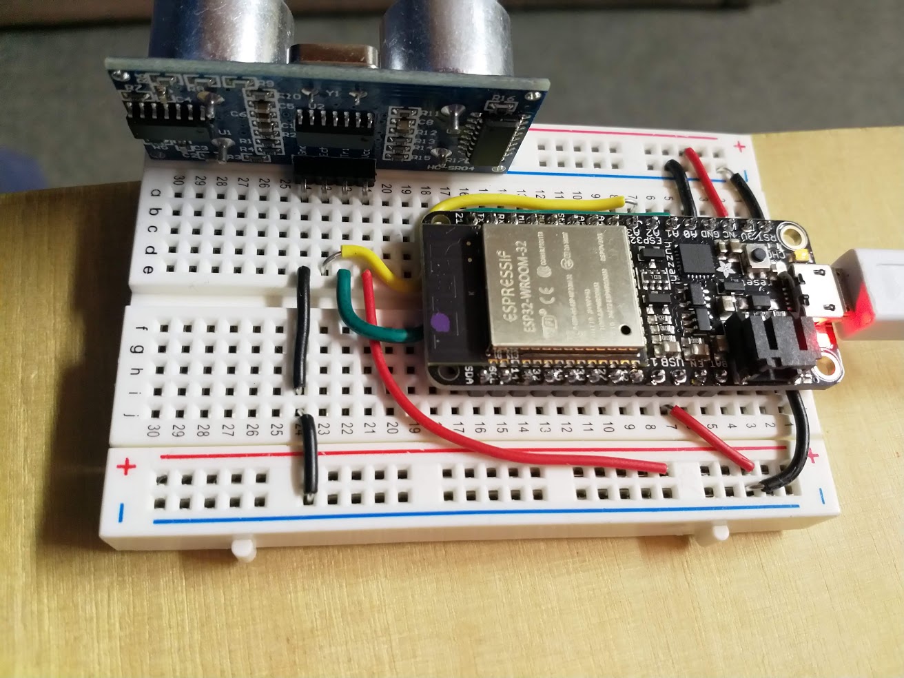